
CCS2 vs GB/T vs CHAdeMO: Choosing Connectors for a Mixed EV Fleet
Choose the interfaces your vehicles need—and the evidence your procurement decision needs.
CCS2, GB/T DC and CHAdeMO are different vehicle-to-charger interfaces, not interchangeable power labels. Choose the connector mix from the exact vehicles you must serve, then verify the charger implementation and simultaneous-session behaviour. A matching plug, a high kW rating or an OCPP claim alone does not establish that the complete charging session will work.
CCS2 vs GB/T vs CHAdeMO at a glance
The practical question is not which standard is “best.” It is which configuration can serve your vehicles during the operating window you actually have. Keep connector identity separate from power, software and the number of vehicles charging together.
| Interface | What to identify first | What to request from the supplier | What not to assume |
|---|---|---|---|
| CCS2 / Combo 2 | Exact vehicle variant with a CCS2 DC inlet | Supported vehicle communication implementation, firmware and representative-vehicle test record | CCS1 and CCS2 are the same physical interface, or every CCS2 car accepts the charger’s nameplate power |
| GB/T DC | Vehicle’s DC interface and applicable implementation/edition | Coupler and communication editions, vehicle/version matrix and session evidence | A Chinese-brand vehicle necessarily has a GB/T inlet |
| CHAdeMO | Exact model, model year, market and inlet | Supported implementation, available hardware and tested vehicle combinations | Every vehicle from one brand uses CHAdeMO, or all versions support the same functions |
CharIN’s connector reference distinguishes the connector systems. Use it for terminology, not as a substitute for the vehicle’s market-specific documentation. For detailed individual checks, see our CCS buyer’s guide, GB/T charger guide and CHAdeMO vehicle guide.
Start with the vehicle roster, not the country map
Country maps are useful context but a poor purchase order. Imported vehicles, export variants and vehicles already in service can give one depot several different requirements. Even a correct description of the national market does not identify the inlet on your next delivery.
A concrete counterexample: BYD’s Singapore 2025 ATTO 3 specification sheet lists CCS2 for DC charging. That establishes the interface for the documented variant; it does not establish the connector on every ATTO 3 worldwide. It is enough to show why “Chinese brand, therefore GB/T” is not a reliable procurement rule. BYD Singapore specification sheet.
Create one row for each materially different vehicle configuration. A photograph helps identify the inlet, but it should accompany, not replace, the manufacturer’s documentation.
| Vehicle-record field | Evidence to collect | Decision it supports |
|---|---|---|
| Make, model, year and original sales market | Market-specific manual/specification and fleet asset reference | Avoids treating differently equipped variants as one vehicle |
| Actual DC inlet | Clear inlet photograph plus documentation | Establishes the physical connector candidate |
| Charging requirements | Vehicle charging specification and any manufacturer restrictions | Defines the voltage/current and communication checks |
| Relevant software version | Available vehicle information and supplier test reference | Makes the compatibility claim reproducible |
| Arrival, departure and energy needed | Fleet schedule and operating records | Determines whether a connector is needed concurrently or only occasionally |
| Test availability | Named representative vehicle or declared gap | Separates tested combinations from proposed combinations |
Do not send unnecessary driver information or complete vehicle identifiers in an initial enquiry. An anonymized fleet reference is usually enough to start the engineering discussion. Share sensitive identifiers only through an agreed channel if required for exact variant verification.
What if the future vehicles have not been delivered?
Mark those rows provisional. Request the ordered variant’s documentation and agree how compatibility will be accepted after delivery. A simulator can test specified charger behaviour, but it is not evidence that an unavailable production vehicle has completed a session. Keep this distinction in the quotation, acceptance plan and payment milestones.
Separate vehicle compatibility from backend connectivity
There are two different conversations in a networked charging session: the vehicle communicates with the charger, and the charger communicates with its management system. Fixing one does not automatically fix the other.
implementation
functions
One successful connection does not prove the other. Record both results.
CharIN’s explanatory CCS design guide describes high-level communication using PLC alongside lower-level signalling. The Open Charge Alliance defines OCPP for communication between charging stations and management systems. An OCPP version on a data sheet is therefore not proof that a charger can communicate with a different vehicle interface. CharIN CCS design guide, 2019; OCA protocol overview.
For GB/T, ask for the actual standard references and implementation scope, not simply “latest GB/T.” The official catalogue separately identifies the DC coupler standard GB/T 20234.3-2023 and the communication standard GB/T 27930.2-2024 for applications using GB/T 20234.3. A standards catalogue entry does not prove which edition your vehicle or charger implements. Coupler record; communication record.
CHAdeMO also has version-specific development: the association announced version 2.1 in June 2026. That is not a reason to assume an older charger or vehicle gains new capabilities automatically. Ask for the supported combination and test evidence. CHAdeMO announcement.
For the station/backend side, name the required functions: authorization, transaction records, remote operations and any charging-management functions you actually need. Test them with the intended backend. A vehicle starting a local session and the backend recording that session correctly are separate acceptance results. The OCA’s CHAdeMO/OCPP explanation is useful precisely because it separates those boundaries.
Choose the connector mix for the busiest relevant window
Annual fleet percentages can hide a daily queue. Ten percent of vehicles needing a different interface may be easy to serve if they arrive throughout the day, but difficult if they all return before one short departure window.
Use the operating schedule to answer three questions: which vehicles overlap, how much energy must each receive, and what happens when the shared unit is unavailable? This is connector planning joined to fleet charging operations, not a substitute for an electrical site design.
HOLD: An unconfirmed variant, undocumented adapter or unknown simultaneous mode remains an open item.
| Fleet situation | Configuration direction to investigate | Evidence needed before choosing | When to stop |
|---|---|---|---|
| One confirmed interface across the working fleet | Standardize the required bays on that interface | Vehicle/version tests and capacity against the schedule | Future unconfirmed vehicles are being treated as guaranteed compatible |
| Two interfaces, sessions seldom overlap | A qualified multi-interface unit or separately scheduled provision | Which outputs can operate, changeover behaviour and booking constraints | Supplier says “two connectors” but cannot explain simultaneous operation |
| Two interfaces with overlapping departures | Independently usable charging paths or documented shared capacity | Per-output allocation during the real overlap case | A nominally flexible unit cannot meet both vehicles’ requirements together |
| Small legacy fleet with uncertain retirement date | Retain or procure bounded support, subject to an explicit review date | Actual utilization, downtime exposure and support availability | A new configuration relies on an unverified conversion adapter |
| High consequence of one cabinet outage | Evaluate separate failure domains or an operational fallback | Dependency map and a workable outage scenario | Extra cables are being counted as independent redundancy |
Hypothetical example: six CCS2 vehicles and two GB/T vehicles are on a depot roster. This count alone cannot determine the number of chargers. If the two GB/T vehicles must charge at the same time, a unit with one usable GB/T path will not provide two concurrent GB/T sessions. If their windows do not overlap, scheduling may change the requirement. Energy demand, available power and service continuity still need checking in both cases.
Do not label a multi-connector cabinet “future-proof” without stating its expansion boundaries. Ask what can be changed in hardware, what requires new certification or testing, and which commitments are merely roadmap proposals. Our dual-gun guide covers the separate issue of output allocation.
Are adapters an acceptable shortcut?
Do not treat an adapter as a passive shape converter. Between different DC charging systems, physical connection is only part of the problem; communication, protective behaviour and the exact vehicle/charger combination also matter.
Before considering a commercial adapter, obtain written compatibility documentation identifying the adapter model, vehicle variant, charger implementation, limitations and intended market. Ask how faults, session termination and software changes are handled. Check manufacturer instructions and applicable local requirements with the responsible project parties.
Reject an adapter-based design if the supplier cannot name the supported combination, if any necessary manufacturer authorization is missing, or if there is no practical acceptance and support route. Do not improvise wiring or bypass interlocks to make a session start. For routine fleet operation, compare the operational burden against a supported native-interface option rather than assuming the cheapest accessory produces the lowest project cost.
Adapter availability is not the same as qualification. This guide does not approve any particular adapter, and HG Power’s portfolio range is not evidence of adapter support.
A real specification sheet: what “CCS2 + CCS2” proves
The HG Power Genesis 60 kW CCS2 specification sheet reviewed for this article lists “CCS2+CCS2,” two outputs and a maximum power of 60 kW. These are separate fields. Together they identify the documented connector arrangement and nameplate limit; they do not establish 60 kW per connector during simultaneous charging.
The same sheet marks backend protocol options as optional. An option listed in a catalogue must be confirmed in the quoted configuration before it becomes a project commitment. This is why our comparison separates interface, implementation and session evidence instead of compressing them into one “compatible” checkbox.
| Document statement | Safe procurement reading | Additional deliverable |
|---|---|---|
| CCS2 + CCS2; two outputs | The named sheet describes two CCS2 outputs | Exact order configuration and vehicle compatibility scope |
| Maximum power: 60 kW | A maximum nameplate field for the documented model | Output allocation under one-session and two-session conditions |
| Backend protocol options | Options appear in the document | Selected implementation and required-function test results |
| HG Power portfolio: 40–480 kW | Portfolio-level power range | Model-specific interface, electrical, thermal and conformity evidence |
This sheet does not document a three-standard charger. We do not extend its fields to GB/T or CHAdeMO products. Request the applicable model documentation for the connector mix under consideration. Likewise, choose a power band only after defining vehicle needs and site constraints; connector choice alone does not determine delivered charging power.
Turn compatibility into an acceptance record
Before ordering, agree what constitutes a successful test and who supplies the representative vehicles, backend access and test equipment. The following is a proposed procurement checklist, not a claim that these tests have already been performed on a particular HG Power configuration.
- Freeze the configuration. Record charger model, connector arrangement, firmware, backend configuration and tested vehicle variants. Identify any untested rows.
- Complete a normal session. Observe connection, authorization, charging, controlled stop and release using approved procedures. Record relevant session data and any limitations.
- Test the overlap case. Start the required simultaneous sessions, observe allocation and terminate one session. Verify the remaining session’s behaviour against the agreed specification.
- Verify operational records. Check that the intended backend receives the necessary transaction information and that required functions behave as specified.
- Use an approved exception test plan. Qualified personnel should define safe tests for relevant communication interruptions, recovery and protection functions. Do not create hazardous faults in the field merely to “see what happens.”
- Repeat site-dependent checks after installation. Confirm cable access, bay geometry, site configuration and the representative session on the installed system. Record factory and site results separately.
- Define change control. Specify which firmware, vehicle, backend or hardware changes require review and retesting. Keep an owner for each unresolved issue.
Factory acceptance can establish behaviour in the factory test arrangement; it cannot confirm the geometry or operating conditions of a site that has not yet been commissioned. Use the station planning guide and component-boundary guide to allocate responsibilities outside this connector comparison.
If a session fails, what should the team check?
Treat the causes below as investigation paths, not remote diagnoses. Electrical inspection and controlled tests belong to qualified personnel following manufacturer procedures.
| Observed symptom | Possible boundary to investigate | Evidence to collect | Procurement action |
|---|---|---|---|
| Connector cannot be used as expected | Wrong vehicle variant, interface or bay access | Inlet identification, order specification and safe access inspection | Correct the requirement; do not force the connection |
| Connection is possible but charging does not start | Authorization, vehicle/charger communication or configuration | Time-matched vehicle, charger and backend records | Escalate with the exact tested combination, not only a photograph |
| One vehicle works; another nominally similar vehicle does not | Different market variant, software or implementation | Separate vehicle rows and repeatable observations | Narrow the compatibility claim until the second row is qualified |
| Each output works alone but overlap disappoints | Shared allocation or unsupported simultaneous mode | Both-session logs and declared allocation behaviour | Reconcile the architecture with the operating schedule |
| Vehicle charges but backend data is incomplete | Station/backend integration or selected functions | Station records compared with backend records | Resolve the OCPP/function boundary separately |
| A previously working combination fails after an update | Changed vehicle, charger or backend software | Before/after versions and controlled retest | Apply the agreed support and change-control process |
A connector that fits still needs a usable bay
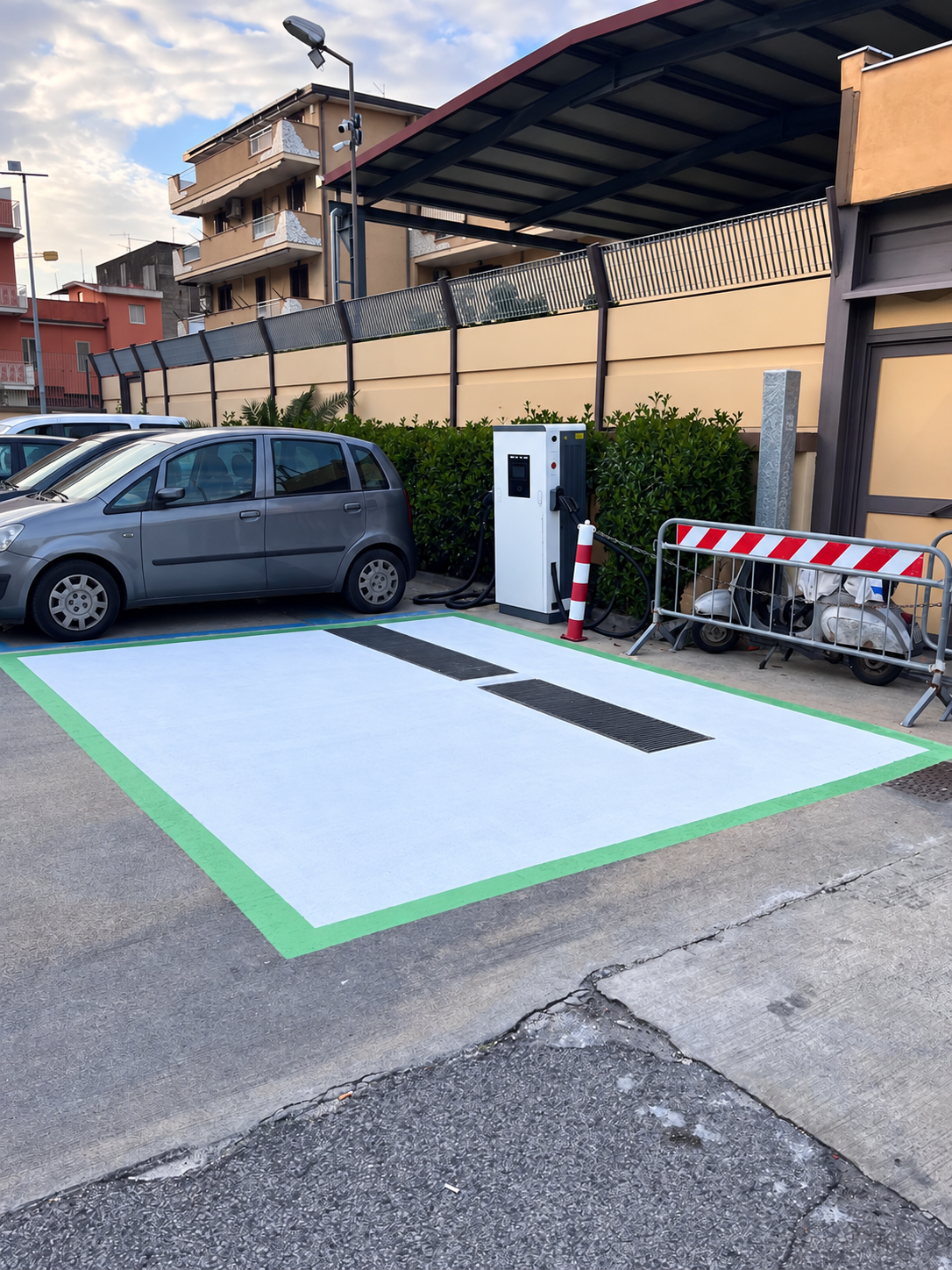
The supplied Italy installation-context image illustrates a practical point: cabinet position, parked vehicles and cable approach belong in the review. It does not prove the connector standard, output power or acceptance status of the equipment shown.
Ask for a bay drawing showing the intended parking orientation and inlet positions of representative vehicles. Verify the cable can be used according to its instructions without creating an avoidable route obstruction. A compatible interface on an inaccessible cabinet is not a usable charging service.
This is also why extra connectors do not necessarily provide resilience: outputs may share power equipment, controls or other dependencies. Document those dependencies and the fallback procedure instead of counting visible cables as independent chargers. For the distinction between nameplate and sustained delivery, see HPC versus DC charging.
Frequently asked questions
Is CCS2 better than GB/T?
Not as a universal procurement answer. A supported interface for the exact vehicle is the starting point. Then compare implementation evidence, usable capacity, operational requirements and support. A well-documented charger with the wrong native interface is not a better choice for that vehicle.
Can a CCS2 vehicle charge at a GB/T DC charger?
Do not assume direct compatibility. An adapter-based proposal needs documented approval and qualification for the exact combination, including communication and safe operating behaviour. This article does not endorse an adapter or recommend converting an interface yourself.
Does CHAdeMO still need to be included in a new station?
Include it when documented vehicle demand and the operating plan justify supported provision. Do not add it only because a generic global checklist includes it, or remove it solely because another standard is growing. Record the legacy fleet’s expected service period and review the decision as demand changes.
Does OCPP make different charging connectors compatible?
No. OCPP addresses the station-to-management-system connection. Vehicle-side compatibility must be established separately. Both need testing in a networked deployment, but passing one is not evidence that the other works.
Will a charger with three connector types charge three cars together?
The connector count does not answer that question. Request the permitted simultaneous combinations, power allocation and any mutual exclusions for the exact configuration. Test the combination your operating schedule requires.
Can I specify one connector type for every country?
Only if the actual vehicle requirements and destination conditions support that choice. Brand origin and broad regional trends are insufficient. Build the vehicle roster for each project, and verify local installation and conformity requirements with the responsible professionals.
Send these ten inputs for a configuration-specific response
- Installation country and site type.
- Vehicle make, model, model year and sales-market variant.
- Documented DC inlet type and a clear inlet photo for each distinct variant.
- Vehicle charging requirements and known manufacturer restrictions.
- Number of vehicles by variant, including planned additions separately.
- Arrival/departure windows and energy needed per vehicle.
- Required simultaneous-session combinations.
- Available site supply information and bay layout.
- Required backend, authorization and operational functions.
- Representative vehicles available for testing and the acceptance/support responsibilities.
Ask the response to identify the proposed model, supported combinations, allocation behaviour, options, exclusions and remaining evidence gaps. An unsupported row should stay visible as an open item, not disappear behind the word “compatible.”
About this guide and its evidence
Prepared for HG Power using official standards/association resources, a market-specific vehicle sheet and the named Genesis 60 kW product sheet. The vehicle roster, routing process and acceptance checklist are editorial procurement tools, not certification documents or claims of completed customer tests. The project image is supplied installation-context material with identifying details removed.
Technical reviewer assigned: Marvin. Review approval for this draft is pending. No professional credential is implied. Source review date: 14 October 2026. The portfolio range is 40–480 kW; actual interfaces, options and conformity remain configuration- and destination-specific.
Linked primary sources beside the relevant claims form the source list. Request the applicable product documentation when evaluating a quotation. This guide is not an electrical design, an adapter authorization or a guarantee of compatibility with an untested vehicle.
Bring the vehicle roster. Ask for the proof.
Send the ten project inputs and request a model-specific response with supported combinations, exclusions and an acceptance plan.