
Dual Gun Charging: Power Sharing, Simultaneous Output and RFQ Guide
Separate cabinet power, connector ceilings and simultaneous A/B delivery—then convert every allocation claim into an acceptance test.
Quick answer: A dual gun charger has two charging connectors, but that alone does not tell you what happens when two vehicles plug in. The advertised kW may be the cabinet total, a single-connector maximum, or—in some designs—a simultaneous rating. Before buying, require four numbers: cabinet rated output, maximum output per connector, two-connector aggregate output, and minimum guaranteed output per connector during concurrent charging.
For a commercial or fleet project, the useful question is not “Does it have two guns?” It is: What power will connector A and connector B deliver in every operating state that matters to us—and how will the supplier prove it?
This guide turns that question into an RFQ and acceptance method. It focuses on DC dual-connector equipment; dual-port AC products use the same basic distinction between connector count and available site power, but their electrical architecture and duty cycle are different.
What does dual gun charging actually mean?
“Dual gun” usually means one charger or dispenser presents two charging cables. It is a physical description, not a complete performance specification.
Depending on the product architecture, the two connectors may:
- charge two vehicles simultaneously from a shared DC power pool;
- divide available power in fixed steps;
- reallocate power as vehicle demand changes;
- prioritize one connector or user class;
- operate one at a time; or
- connect to separate power channels behind one enclosure.
The phrase is also used for dual-port AC chargers. Therefore, an RFQ should state AC or DC, connector standard, number of simultaneously active sessions, and the required power behavior. If vehicle compatibility is still open, resolve it in the CCS charger buyer's guide before treating a cable count as coverage.
The official IEC synopsis for IEC 61851-23:2023 includes multi-side-B separated DC EV supply equipment in its updated scope. That is useful context: multiple outputs are an engineering and conformity matter, not merely a cabinet option.^1
Use the Four-Number Check before comparing quotations
Four values prevent most dual-gun specification ambiguity.
| Number | What it means | What to request |
|---|---|---|
| 1. Cabinet rated output | Maximum DC power available from the power cabinet under stated conditions | Rated kW plus input, ambient, altitude and derating conditions |
| 2. Per-connector ceiling | Maximum voltage, current and power one connector may deliver | V/A/kW limits for A and B, including cable/cooling option |
| 3. Two-port aggregate limit | Maximum combined output while both sessions are active | Guaranteed A + B limit under stated test conditions |
| 4. Concurrent floor | Minimum power guaranteed to each port in an agreed two-vehicle case | A/B minimums, allocation rule, response time and exceptions |
Do not fill a missing cell with an assumption. A “240 kW dual gun charger” could mean a 240 kW shared cabinet with two outputs; it does not automatically mean 240 kW on each connector at the same time.
The fourth number is frequently omitted, yet it matters to fleets. An operator may accept demand-following allocation but still require, for example, a minimum service level for a priority vehicle. That floor must be technically feasible at the specified voltage, current, site cap and cabinet condition.
Two cables need four power answers
≠
≠
+
If one number is missing, the simultaneous result is still unspecified.
Why the nameplate kW is not the delivered power
For a DC session, the electrical relationship is:
Power (kW) = voltage (V) × current (A) ÷ 1,000
But multiplication only gives a power value at a particular voltage and current. It does not prove that the vehicle, cable, connector, charger, shared power pool or site can sustain it.
For each active connector, use this decision rule:
Delivered power ≤ the lowest active limit among:
- the vehicle's present request;
- the connector's voltage/current/power ceiling;
- the power allocated to that connector;
- the cabinet's remaining available output; and
- the site's active power limit.
Temperature, altitude, cooling state, module availability and control limits can lower one or more of these ceilings. This is why a proper HPC versus DC charging comparison examines voltage, current, cooling and site fit instead of relying on a kW label.
How can two connectors share power?
There is no safe category-wide assumption. Common control concepts include the following, but the exact implementation must be documented for the quoted model.
Fixed allocation
Each connector receives a predefined portion of the available power when both are active. This is predictable, but unused capacity on one side may remain unavailable to the other unless the design supports reallocation.
Equal allocation
The available pool is divided equally while both sessions request enough power. Equal sharing is simple to explain, but it may waste opportunity when one vehicle cannot use its share.
Priority allocation
One connector, fleet class or session receives priority subject to agreed limits. This can suit scheduled fleets, but the priority rule, fallback behavior and operator controls must be explicit.
Demand-following allocation
The controller can adjust allocation as vehicle requests change. If one vehicle tapers, available capacity may move to the other—subject to module granularity, connector limits, site limits and the implemented control policy.
Do not accept “intelligent power sharing” as the specification. Ask for the state table: trigger, allocation, granularity, transition time, priority and fallback.
A 240 kW dual-gun example: three different outcomes
The following examples are hypothetical calculations, not performance promises for an HG Power model.
Assume a 240 kW cabinet, two connectors each capable of up to 200 kW under the test voltage/current conditions, and no additional site cap.
| Operating state | Vehicle A request | Vehicle B request | One possible compliant policy | Why the result is not automatic |
|---|---|---|---|---|
| Only A active | 180 kW | — | A 180 / B 0 | A remains below its 200 kW port ceiling and the 240 kW cabinet limit |
| Both request high power | 180 kW | 140 kW | A 120 / B 120 under equal sharing | A different priority policy could allocate the same 240 kW total differently |
| B demand falls | 180 kW | 40 kW | A 180 / B 40 under demand-following allocation | This requires the design to reassign unused capacity and A to accept it |
Now add a 180 kW site limit. Even though the cabinet is rated 240 kW, the two sessions together must remain within the active 180 kW cap. Depending on policy, that could be 90/90, 120/60 or another agreed split.
The lesson is simple: one cabinet rating can produce several valid A/B outcomes. Only the quoted allocation schedule and witnessed test distinguish them.
Specify transitions, not only the best case
Specify a two-session state table
A concise state table is more useful than several pages of adjectives.
| State to specify | Required supplier response | Evidence to retain |
|---|---|---|
| A active, B idle | A maximum and conditions | HMI/meter trace and test-load record |
| A and B request equally | A/B allocation and combined limit | Synchronized A/B power trace |
| A and B request unequally | Allocation policy and unused-power behavior | Request versus delivered-power trace |
| One vehicle tapers | Reallocation trigger, step and time | Timestamped transition record |
| Site cap changes | Local/CSMS response and safe fallback | Command, acknowledgement and meter trace |
| One module unavailable | Remaining capacity, alarms and allocation | Fault simulation and recovery record |
| One connector faults | Session isolation and other-port behavior | Alarm, stop logic and unaffected-port trace |
| Communication is lost | Local limit, session policy and recovery | Disconnect/reconnect test record |
This table also exposes a procurement error: asking only for the best case. A commercial duty cycle includes overlap, taper, constraints and faults.
Measure throughput across the overlap window
Two connectors can improve access without doubling installed power. Whether that creates value depends on arrivals, dwell time, vehicle acceptance and allocation.
Build the requirement from the operating window:
- list vehicle classes and the energy each must receive;
- estimate when sessions overlap;
- map each vehicle's voltage/current acceptance and charge curve;
- apply the cabinet and site limits;
- simulate the chosen allocation rule; and
- verify that the required energy is delivered before departure.
For a depot, a guaranteed overnight energy target may matter more than peak kW. For a public site, simultaneous access and a clear driver experience may matter more. For heavy vehicles with short dwell windows, connector current, cable management and sustained output can dominate. Use the electric-car charging-time method for time estimates, but replace generic assumptions with the actual fleet and allocation data.
Do not claim that dual gun “halves queues.” A second active connector can reduce blocking in some arrival patterns, but queue performance is a system outcome, not a cable-count guarantee.
Check the vehicle, connector and parking envelope
Power allocation is only useful if both vehicles can connect and accept it.
Vehicle acceptance
Collect the battery voltage window, maximum requested current, charging curve, target state of charge and temperature constraints for representative vehicles. A high cabinet rating cannot override a lower vehicle request.
Connector and cable ceiling
State the connector standard for each cable and the continuous/peak current conditions of the selected cable system. Do not mix a connector standard claim with a destination certification claim. The exact SKU, options and market evidence must match.
Reach and bay geometry
Verify cable length, exit direction, parking orientation, inlet location, bollards, wheel stops and accessible routes. Test the least convenient expected vehicle, not only a passenger car parked perfectly. Cable-management and truck turning needs belong in the DC fast charger station design.
Thermal and environmental conditions
Ask for the output/derating envelope at the site's high ambient temperature and altitude. A two-port test at comfortable factory conditions does not alone prove the hot-site result.
What OCPP can—and cannot—prove
OCPP connects charging stations and charging-station management systems. The Open Charge Alliance states that OCPP 1.6 supports smart charging for load balancing and charging profiles, while OCPP 2.0.1 adds smart-charging functionality.^2 OCA also publishes guidance for representing multiple connectors per EVSE in earlier OCPP versions.^3
That supports useful controls, but an OCPP version label does not answer all dual-gun questions. Confirm:
- the exact protocol version and transport;
- which smart-charging functions are implemented and enabled;
- how the two connectors are represented in the data model;
- whether a site or connector limit can be set;
- whether meter values for A and B are separately reported;
- how local allocation interacts with a CSMS profile;
- the offline limit and recovery behavior; and
- successful tests with the target CSMS and firmware.
OCPP 1.6 and 2.0.1 are not mutually compatible protocols, according to OCA.^2 Treat migration or multi-backend support as a planned integration task, not a checkbox.
Most importantly, a CSMS power limit and an internal module-allocation algorithm are different layers. The backend may define the envelope while the charger locally distributes power. Require a message-to-meter test if that relationship matters to the project.
Integrated dual-gun or separated architecture?
The connector count does not decide the enclosure architecture.
| Question | Integrated dual-gun cabinet | Separated power cabinet and dispenser(s) |
|---|---|---|
| Typical reason to consider | Two adjacent bays; compact procurement boundary | More flexible parking layout or multiple dispensers |
| Power path to document | Internal modules/switching to two cables | Central power pool, distribution and dispenser limits |
| Site-layout focus | Cabinet footprint, service clearances and cable reach | Cabinet location, DC distribution route and dispenser placement |
| Failure-domain question | What remains available after a module/port fault? | What remains available after cabinet, feeder or dispenser fault? |
| Expansion question | Can modules or cabinets be added? | Can dispensers/outputs be added within cabinet and site limits? |
Neither architecture is universally better. Compare accepted energy, bay geometry, maintainability, redundancy, civil/electrical scope and future phases. See HG Power's separated DC charging station for a product-category example, then request the exact project configuration.
What HG Power's current documents establish
HG Power's public DC portfolio spans 40–480 kW. That range describes the portfolio; it is not one common specification.
The visually reviewed CCS1 manual pages cover the named ANSI-DCL120B, DCL180B, DCL240B, DCL360B and DCL480B family. They state 120/180/240/360/480 kW, 200–1000 V DC, maximum 250 A with 350 A optional, dual CCS1 connectors, OCPP 1.6J, IP54 and air cooling.
Separately reviewed Genesis CCS2 sheets state:
| Named sheet | Rated output | Interface | Current ceiling shown | Outputs shown |
|---|---|---|---|---|
| Genesis 60 kW | 60 kW max | CCS2 + CCS2 | 200 A max/connector | 2 |
| Genesis 120 kW | 120 kW max | CCS2 + CCS2 | 250 A max/connector | 2 |
| Genesis 180 kW | 180 kW max | CCS2 + CCS2 | 250 A max/connector | 2 |
| Genesis 360 kW | 360 kW max | CCS2 + CCS2 | 350 A max/connector | 2 |
These documents establish connector count and model-family electrical ceilings. They do not state a universal simultaneous A/B power schedule. That schedule must be supplied for the exact quotation, hardware, firmware and configuration. Review the current DC charger specifications and ask HG Power to reconcile any project-specific value before approval.
Field evidence: what the project photographs prove
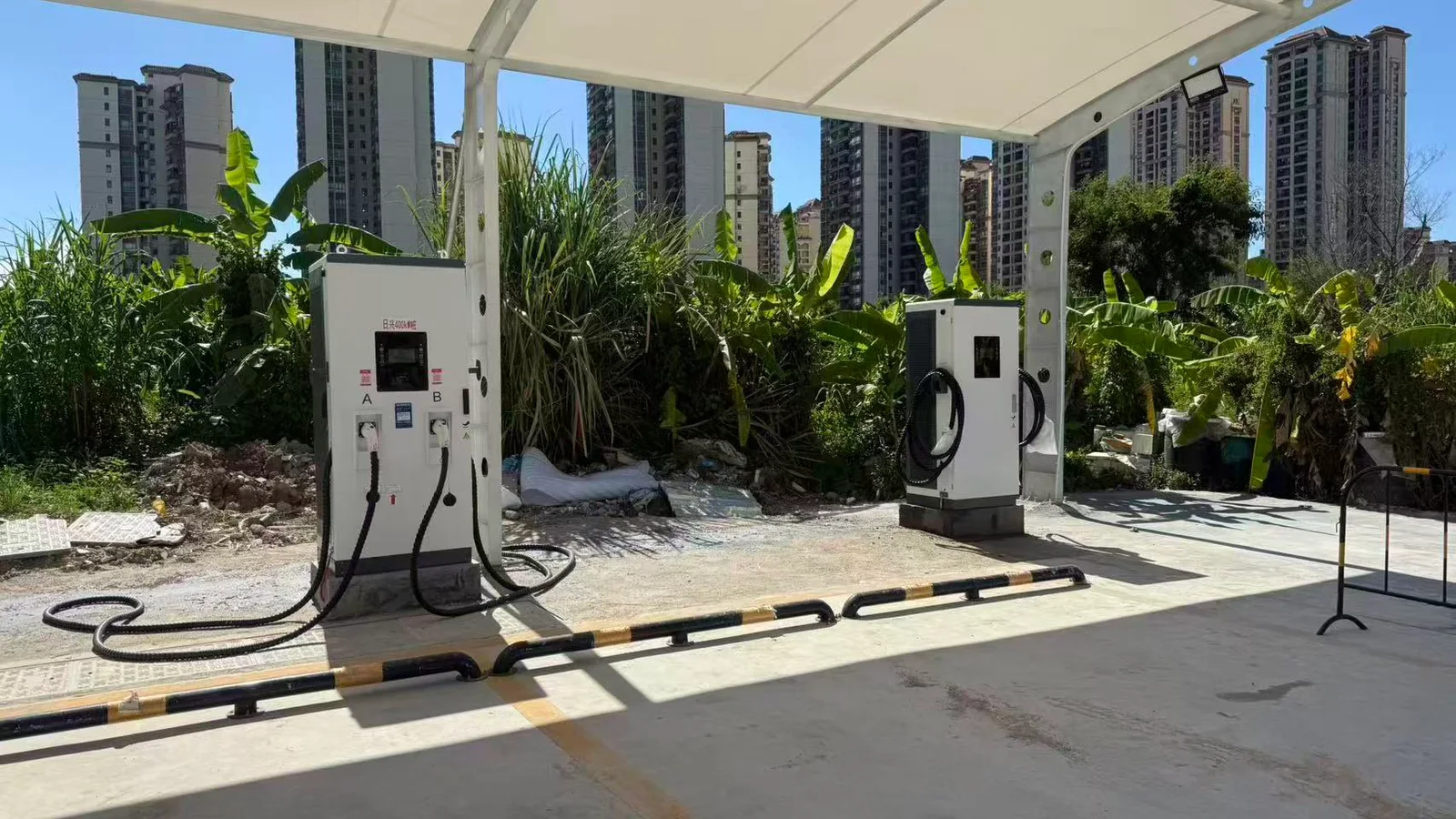
The supplied project note for Rixing New Energy Chengnan Charging Station in Yangjiang lists five 120 kW dual-gun units, one 240 kW dual-gun unit and one 400 kW dual-gun unit. Supplied photographs show installed cabinets with two visible cables and the surrounding bay arrangement.
This is useful evidence that a mixed dual-gun configuration was deployed. It is not evidence of simultaneous delivered power, utilization, charge time, uptime or customer endorsement. Those require meter traces, test records and operating data.
That distinction should govern every case study: photographs establish visible context; controlled records establish performance.
Put this allocation matrix in the RFQ
Ask every bidder to complete the same matrix for the exact SKU.
| RFQ field | Bidder must state | Acceptance evidence |
|---|---|---|
| Exact model/build | Model, hardware revision, firmware and options | Nameplate, BOM/configuration record |
| Cabinet output | Rated and derated kW by input/ambient/altitude | Datasheet plus witnessed load test |
| Connector A/B | Standard, voltage, current and power ceilings | Matched cable/connector document |
| Simultaneous operation | Whether two active sessions are supported | Dual-load or two-vehicle test |
| Aggregate ceiling | Maximum A + B under stated conditions | Synchronized meter trace |
| Allocation policy | Fixed, equal, priority or demand-following | State table and configured parameters |
| Minimum service | Guaranteed A/B floors in named cases | Pass/fail thresholds in FAT/SAT |
| Reallocation | Trigger, granularity, delay and hysteresis | Taper/demand-step test |
| Site control | Local cap, meter input and CSMS behavior | Limit-change test |
| Fault behavior | Module/port/comms fault, alarms and remaining output | Fault-injection record |
| Backend | OCPP version, profiles, connector model and target CSMS | Interoperability log/test report |
| Destination | Applicable standards, evidence owner and exact SKU match | Independently verified documents |
This matrix makes quotations comparable. It also prevents a general brochure from silently replacing a model-specific answer.
Make the allocation promise observable
Run the Four-Case Allocation Test at FAT and SAT
At minimum, witness four cases using agreed loads or representative vehicles.
Case 1 — single-session ceiling
Run connector A, then B, through the agreed voltage/current points. Record requested versus delivered voltage, current and power, cabinet input, temperatures and alarms.
Case 2 — equal concurrent demand
Make both sides request enough power to reach the agreed shared limit. Verify A, B and A + B against the allocation schedule and tolerance.
Case 3 — unequal and changing demand
Reduce one side's request in controlled steps. Verify whether, how fast and in what increments unused power moves to the other connector. Repeat with A and B reversed.
Case 4 — constrained or degraded operation
Apply an agreed site cap, communication interruption or permitted module-unavailable simulation. Verify safe limits, alarms, remaining service and recovery.
FAT proves the controlled factory build. SAT repeats the relevant cases after site power, networking, CSMS, cables and environment enter the system. Retain configuration files, firmware identifiers, raw logs and signed results—not only a pass certificate.
Diagnose a slow connector without guessing
| Observation | Possible cause | First evidence to check |
|---|---|---|
| Power falls when B starts | Intended shared allocation or site cap | A/B/aggregate traces and configured policy |
| One vehicle stays low while capacity appears free | Vehicle request, port current limit or fixed allocation | EV request, connector current and allocation state |
| Both ports fluctuate | Changing vehicle demand, module steps or upstream control | Timestamp-aligned EVSE, CSMS and meter logs |
| Power falls at high ambient | Thermal derating or cooling condition | Temperature, fan/coolant status and derating curve |
| Backend limit has no expected effect | Profile/configuration/data-model mismatch | OCPP messages, acknowledgements and local limit |
| Other port stops after one-side fault | Shared protection/failure-domain behavior | Alarm code, protection design and fault test |
Observed low power is not automatically a charger fault, and it is not automatically “normal power sharing.” Diagnose against the agreed limits and trace data.
When is a dual-gun charger the right choice?
A dual-gun architecture is a strong candidate when two bays have meaningful overlap, the shared power pool matches required energy delivery, cable reach is practical, and the acceptance plan proves the desired allocation.
Consider two independent chargers or a separated system when:
- each bay needs an independently guaranteed high output;
- a shared cabinet creates an unacceptable failure domain;
- bays are too far apart for safe cable routing;
- expansion calls for more than two simultaneous sessions;
- maintenance isolation is more important than enclosure consolidation; or
- the site power strategy is better served by several independently controlled EVSEs.
The final decision belongs in the project model, not in a generic feature comparison. The commercial EV charger buyer's guide provides the broader procurement sequence.
Dual gun charging FAQ
Can a dual gun charger charge two cars at the same time?
Some can; the label alone does not prove it. Require the exact model to state two-session support, A/B limits, combined output and the allocation policy, then witness the agreed case.
Does a 120 kW dual gun charger give 120 kW to each vehicle?
Not necessarily. If 120 kW is the cabinet total, two simultaneous sessions share that available pool subject to port, vehicle and site limits. Only a model-specific simultaneous rating can establish another result.
Is power always split 50/50?
No. A product may use fixed, equal, priority or demand-following allocation. Ask for the state table and do not infer the policy from the number of cables.
What happens when one EV begins to taper?
In a demand-following design, some unused power may be reassigned to the other session. The amount and timing depend on vehicle demand, module granularity, port ceilings and the configured algorithm.
Does OCPP control dual-gun power sharing?
OCPP smart-charging functions can set charging limits and profiles, but that does not by itself prove the internal allocation behavior of a particular charger or interoperability with a particular CSMS. Test the complete message-to-meter path.
Which is better: dual gun or two separate chargers?
Neither is universally better. Compare concurrent power guarantees, energy delivered within dwell windows, redundancy, site layout, serviceability, expansion and total installed scope.
What information should I send for a dual-gun quotation?
Send the destination country, vehicle models, voltage/current acceptance, energy and dwell targets, overlap schedule, required A/B service floors, connector mix, site capacity, ambient/altitude, CSMS/OCPP needs, cable/bay layout and FAT/SAT cases.
Send the vehicles, overlap window, site cap, connector mix and acceptance cases.
Turn “dual gun” into a testable configuration
For a model-specific proposal, send HG Power:
- destination and responsible conformity route;
- representative vehicle list and charging curves;
- required energy by departure time;
- expected concurrent-session window;
- cabinet, per-port, aggregate and minimum A/B targets;
- connector/cable and parking-layout requirements;
- site power limit and control interface;
- OCPP version, target CSMS and required functions; and
- FAT/SAT thresholds and evidence format.
Request a model-specific dual-gun proposal. The response should bind the requested behavior to the exact model, hardware, firmware, options and test plan.
Reviewed by Marvin. Review scope: technical logic, source boundaries and procurement usability. This review line does not add an unverified professional title, certification or third-party endorsement.
Sources and related reading
- International Electrotechnical Commission, IEC 61851-23:2023 — DC electric vehicle supply equipment.^1
- Open Charge Alliance, Open Charge Point Protocol overview.^2
- Open Charge Alliance, Multiple Connectors per EVSE.^3
- HG Power, DC fast charger station design guide
- HG Power, HPC vs DC charging
- HG Power, DC charger specifications