
Fleet EV Charging: How to Size DC Chargers, Depot Power and Operations
Turn fleet duty cycles, vehicle acceptance and depot power into a testable DC charging configuration.
Direct answer: Fleet EV charging is not solved by dividing battery capacity by a charger nameplate. A defensible depot design connects vehicle energy demand, return and departure windows, vehicle acceptance, charger output, site capacity, power sharing and operational controls. Start with the fleet mission ledger; then choose the DC architecture and exact charger configuration.
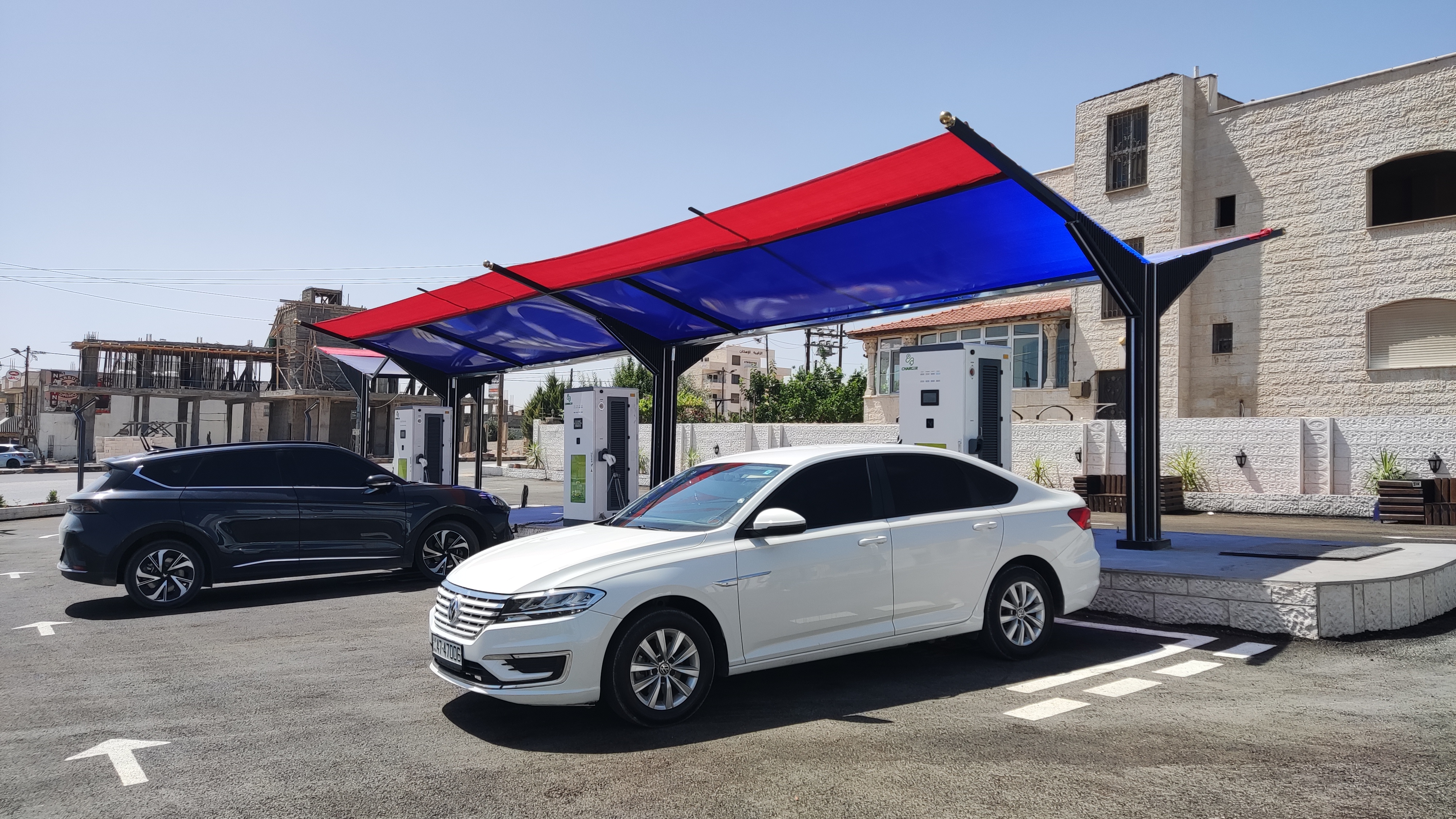
What fleet charging has to deliver
A fleet depot has a service promise: vehicles must leave with enough usable energy for their next duty cycle. That promise may involve vans, buses, trucks, taxis or mixed vehicles, each with a different battery, connector and arrival pattern. DOE fleet planning resources similarly begin with vehicles, locations, equipment and electrical requirements rather than a universal charger ratio.
The procurement question is therefore not “How many chargers do we need?” It is “Which vehicles need how much energy, during which shared windows, through which equipment, under which site limits?”
Build a Fleet Mission Ledger before choosing hardware
| Input | Record for each vehicle group | Why it changes the charger design |
|---|---|---|
| Vehicle duty | route, distance, payload, weather/terrain assumptions | changes energy required per shift |
| Battery and acceptance | usable energy, permitted DC voltage/current, connector and vehicle limit | vehicle can cap delivered power below charger nameplate |
| Return window | earliest arrival, latest departure, dwell duration | determines available charging time |
| Energy target | required departure SOC or kWh, reserve policy | separates mission energy from battery capacity |
| Concurrency | how many vehicles overlap and in what sequence | drives power sharing and queue risk |
| Growth | vehicles, shifts and routes added later | changes service, conduit, transformer and charger expansion |
Do not fill unknowns with a generic “fleet average.” Mark them as verification items for the vehicle OEM, site survey or commissioning test.
The Four-Ceiling Rule
The lowest active ceiling controls the result:
Four ceilings between the grid and the vehicle
| Ceiling | Procurement question | Proof to request |
|---|---|---|
| Vehicle | What DC voltage/current and power envelope does the exact vehicle accept? | OEM datasheet, model-year record or controlled vehicle test |
| Charger | Is the rating per cabinet, output, connector or shared group? | model datasheet, wiring diagram and allocation logic |
| Site | What continuous and concurrent load can the service support? | utility/site survey, single-line diagram and protection study |
| Schedule | Which vehicles charge together, and what is the departure deadline? | dispatch export, arrival/departure timestamps and reserve rule |
Choose the depot architecture around operations
All-in-one DC chargers
The conversion and user interface are in one enclosure. This can simplify a small depot layout, but the RFQ still needs output, connector count, cable reach, service clearance, thermal behavior and future expansion.
Cabinet-and-dispenser systems
Power electronics can be grouped in a cabinet while dispensers are placed near parking bays. This can help a dense depot route power to multiple bays, but the buyer must define cabinet-to-dispenser allocation, simultaneous sessions, cable management and failure isolation.
Mixed AC/DC depot
Some vehicles can use lower-power AC during long dwell while route-critical vehicles use DC. Mixed architecture can reduce peak demand, but it must be tested against the same mission ledger; “overnight” does not automatically mean every vehicle can meet its departure target.
A transparent first-pass sizing method
For a vehicle group, a planning estimate can start with:
Required average charging power ≈ mission energy to replace ÷ effective charging window
The effective window is not simply the time a vehicle is parked. Deduct dispatch constraints, connector availability, queueing, thermal derating, site power-sharing and reserve. Use the estimate to compare scenarios, not to issue a final electrical design.
| Scenario input | Example placeholder | Must be confirmed |
|---|---|---|
| Vehicles in group | 10 | dispatch roster |
| Energy to replace per vehicle | 120 kWh | route and vehicle data |
| Shared window | 6 h | actual return/departure timestamps |
| Concurrent sessions | 4 | bay layout and schedule |
| Planning output | scenario comparison only | charger allocation and site study |
The useful output is a load profile: when sessions start, how many overlap, what power is allocated, and which vehicle is at risk if the site limit is reached.
The Depot Power Ladder
Every RFQ must connect these layers
→
→
→
Backend controls and dispatch rules sit across the chain; they do not replace electrical capacity or vehicle acceptance.
Managed charging can schedule sessions or limit power when vehicles overlap. OCPP may be part of the communications layer, but protocol support is not the same as a complete fleet energy-management solution. Specify the CSMS, authorization, meter data, smart-charging profile, fail-safe behavior and local override.
Connector and vehicle acceptance matrix
| Fleet group | Connector/market | Vehicle limit | Charger-side requirement | Verification |
|---|---|---|---|---|
| Group A | exact connector and region | voltage/current/power envelope | compatible output and cable reach | OEM record + test |
| Group B | exact connector and region | different acceptance curve | allocation policy and priority | controlled session |
| Future group | not yet selected | unknown | do not lock a universal promise | freeze after vehicle award |
Avoid saying “the depot supports all EVs” unless the connector, protocol, electrical envelope and operating test are defined for the actual vehicle set.
How to use the HG Power 40–480 kW portfolio context
HG Power’s public DC portfolio context spans 40–480 kW. That range is a starting point for configuration conversations, not a claim that every model, connector, cabinet or dispenser delivers every value per vehicle or per connector. The exact RFQ should state:
- target output and whether it is cabinet total or connector allocation;
- input voltage/frequency and site-side assumptions;
- connector standard and cable length;
- vehicle groups and acceptance limits;
- static or dynamic power sharing;
- cooling and environmental requirements;
- backend/communications scope;
- FAT, SAT and operational data to be recorded.
Fleet DC charging RFQ and acceptance pack
| Phase | Ask the supplier for | Acceptance evidence |
|---|---|---|
| Configuration | exact model, output basis, connector and limits | signed configuration sheet |
| Integration | single-line, communications and allocation logic | interface review |
| Factory | protection, display, connector, alarms and power allocation | FAT records and test IDs |
| Site | installation, energization and vehicle session plan | SAT checklist |
| Operations | meter/session fields, faults, remote/local control | sample export and recovery test |
Failure diagnostics before buying more chargers
| Symptom | Common boundary to investigate | Next evidence |
|---|---|---|
| Vehicles miss departure | energy target, queue or vehicle acceptance | timestamped session and dispatch comparison |
| Nameplate power is never reached | vehicle curve, thermal state or sharing | vehicle/charger telemetry and allocation log |
| Site trips | service, protection or simultaneous load | single-line and event record |
| New vehicles do not fit | connector or voltage/current mismatch | exact vehicle acceptance matrix |
| Backend shows sessions but not useful energy | meter mapping or data fields | session export and meter validation |
Frequently asked questions
Is DC fast charging always the best fleet option?
No. DC is useful when the mission requires energy in a constrained window. Long dwell, lower-power AC, mixed architecture or scheduled charging may fit another vehicle group. Decide from the mission ledger and site study.
How many kW does a fleet depot need?
There is no responsible universal number. It depends on energy to replace, effective window, concurrency, vehicle acceptance, site limit and future growth. Use a load-profile scenario before selecting a cabinet rating.
Can one 480 kW cabinet charge every fleet vehicle at 480 kW?
No. Vehicle acceptance, connector, cabinet allocation, thermal conditions and site controls can all limit delivered power. Confirm the exact model and session behavior.
Does OCPP solve fleet energy management?
OCPP can define charge-station-to-CSMS communications and relevant control features, but a fleet still needs dispatch rules, site limits, meter data, vehicle records and operational ownership.
Request a fleet charging configuration review
Send the fleet type, vehicle models, connectors, daily routes, energy target, return/departure windows, number of overlapping vehicles, site service information and growth plan. HG Power can then map the 40–480 kW DC portfolio context to a model-specific RFQ and identify the evidence needed at FAT and SAT.
Sources
- DOE FEMP, Electric Vehicle Supply Equipment Planning Form.
- DOE FEMP, EVI-LOCATE planning tool.
- AFDC, Electric Vehicles for Fleets.
- DOE FEMP, Managed EV Charging for Federal Fleets.
- Open Charge Alliance, OCPP.
Technical review: Marvin. This guide is procurement guidance, not a substitute for local electrical engineering, utility approval, vehicle OEM requirements or destination-market compliance review.