
Engineering guide · 2026
DC Fast Charger Station: From Site Data to a Commissioned System
A practical blueprint for freezing duty cycle, electrical capacity, charging hardware, physical layout, digital operation and acceptance evidence.
A DC fast charger station is more than one or more charger cabinets. It is a coordinated system that includes the site power interface, electrical distribution and protection, charging ports, parking geometry, cables, communications, payment or access workflow, and the people and documents needed to operate it.
For a commercial project, the useful question is not simply “How many kilowatts should we buy?” It is:
What combination of energy, concurrent power, vehicle compatibility and operating capacity must the completed station demonstrate—and what evidence will prove it at handover?
This guide turns that question into a six-part Site-to-SAT Blueprint. It also provides a Station Design Freeze Pack and a site acceptance test framework that owners, EPCs, operators and equipment suppliers can use before a quotation becomes an order.
Site electrical design, installation, code compliance and energisation must be completed or approved by appropriately qualified parties for the destination project.
What is included in a DC fast charger station?
Three terms are often mixed together:
- A station is the charging location or site.
- A charging port can charge one vehicle at a time.
- A connector is the physical interface that plugs into a vehicle. A port can sometimes have more than one connector option, but it still may charge only one vehicle at a time.
The practical station boundary may include:
- the utility connection and site service;
- transformer, switchgear, metering, distribution and protection where required;
- an integrated charger cabinet or a power-cabinet-and-dispenser architecture;
- charging bays, foundations, trenching, drainage, impact protection, lighting and signs;
- vehicle connectors, cables and cable management;
- network connectivity, charging-station management system (CSMS), authentication and payment;
- monitoring, fault response, maintenance access, spare parts and operating procedures.
The exact boundary changes by site and country. The Joint Office’s public charging playbook treats charging deployment as a sequence spanning planning, siting, procurement and operation. The DOE Alternative Fuels Data Center likewise places equipment procurement inside a broader process involving site conditions, utilities, installation and operating needs.
That is why a cabinet-only quotation cannot describe a complete station.
Start with station capability, not charger kW
A station has at least four different capacities. They should be sized separately and then reconciled.
| Capacity layer | Design question | Typical evidence |
|---|---|---|
| Energy over time | How many kilowatt-hours must the site deliver during each operating window? | Vehicle schedule, energy-per-session assumptions and load cases |
| Concurrent power | How much combined power can active ports receive under normal and peak cases? | Site limit, charger allocation rules and concurrency test |
| Vehicle interface | Can the output voltage, current, connector and communication match the target vehicles? | Vehicle data, model-specific charger schedule and interoperability tests |
| Operational capacity | Can vehicles enter, connect, pay or authenticate, leave and receive support at the required rate? | Layout review, workflow tests, staffing and escalation plan |
The NLR EVI-EnSitePy tool reflects this systems view: station analysis can consider power rating, port count, connector type, demand profiles, queues and quality of service. Its existence does not remove the need for project engineering; it illustrates why one nameplate number is not enough.
A better starting calculation
For each operating period, record:
- vehicles expected;
- energy required per vehicle;
- arrival distribution, not only the daily total;
- dwell or turnaround limit;
- likely simultaneous sessions;
- exceptions such as late arrivals, low state of charge or cold batteries;
- future fleet or public-demand cases.
Multiplying vehicles by energy per session gives an energy target. It does not by itself determine charger kW or port count. Ten vehicles arriving together create a different station problem from ten vehicles spread across a day, even if total energy is identical.
When DC fast charging may be the wrong answer
If vehicles remain parked for many hours, daily energy demand is modest, or site capacity is severely constrained, a larger number of lower-power AC ports—or a phased mix of AC and DC—may serve the operation better. Use the separate DC fast charger versus AC charger guide to make that architecture decision before specifying a DC station.
The Site-to-SAT Blueprint
A project becomes easier to control when six decisions are frozen in sequence.
| Freeze | Question that must be closed | Controlled output |
|---|---|---|
| 1. Duty cycle | Which vehicles must receive how much energy, when and with what concurrency? | Design basis and operating load cases |
| 2. Electrical system | What power can the site deliver safely, now and after expansion? | Survey, approved one-line and site power boundary |
| 3. Charging system | Which exact hardware and allocation behavior satisfy the load cases? | Model/configuration schedule and technical submittal |
| 4. Physical layout | Can every intended vehicle use the equipment safely and practically? | Issued-for-construction layout and civil details |
| 5. Digital operation | How will sessions start, settle, record, recover and receive support? | Interface-control document and end-to-end test cases |
| 6. Acceptance | What must pass before ownership and warranty responsibility transfer? | FAT/SAT plan, evidence dossier and signed handover |
A “freeze” does not mean a project can never change. It means a change has an owner and its effects on cost, schedule, hardware, civil work, software and acceptance are reviewed before implementation.
Freeze 1: define the duty cycle
Do not ask a charger supplier to infer the fleet from a requested power rating. Create a vehicle-and-operation dataset.
Vehicle fields
- manufacturer and model, where known;
- inlet or connector type;
- battery voltage range or platform;
- maximum accepted DC power and current, if documented;
- battery capacity and normal arrival state-of-charge range;
- inlet position and vehicle dimensions;
- trailers, articulated vehicles or other turning constraints.
Operating fields
- arrivals by hour or shift;
- energy required per session;
- maximum dwell or turnaround window;
- normal and peak simultaneous sessions;
- dispatch priority if available power is limited;
- public, employee, depot, dealer or mixed access;
- seasonal peaks and planned fleet growth.
The output is a short design basis with normal, peak and degraded cases. For example, a degraded case may ask what happens when one port is unavailable or the site operates under a lower temporary power limit. It should state the service consequence rather than assume every vehicle always receives maximum power.
Freeze 2: close the electrical-system boundary
The site’s electrical designer and utility must determine the applicable input arrangement, capacity, protection and code requirements. No single voltage, breaker or transformer formula is valid for every destination.
The electrical freeze normally needs:
- destination country, grid voltage and frequency;
- utility point of connection and available capacity;
- existing transformer, switchboard and meter information;
- maximum site demand and other coincident loads;
- proposed one-line diagram;
- transformer, switchgear and feeder scope where applicable;
- protection, isolation, earthing/grounding and surge strategy;
- power-quality and metering requirements;
- trench routes, cable lengths and civil interfaces;
- spare ways, space and capacity reserved for expansion;
- utility application status and energisation dependencies.
The Joint Office site-evaluation resource highlights utility coordination, power requirements and permitting as feasibility questions. A California corridor study summarized by the National Center for Sustainable Transportation also found that make-ready scope varied greatly and argued for early utility involvement. Its dollar figures belong to those studied California projects and should not be copied into an international budget.
The controlled output is not “grid confirmed” in an email. It is the approved electrical basis and a responsibility boundary showing what the utility, owner, EPC and charger supplier each provide.
Freeze 3: specify the charging system and power allocation
Now the equipment can be matched to the station duty cycle and electrical boundary.
For every quoted model or dispenser, freeze:
- total rated output;
- number of charging ports and installed connectors;
- DC output voltage window;
- maximum current per connector;
- continuous or environmental derating conditions;
- cable length, current rating and cooling method where relevant;
- single-session maximum;
- two-or-more-session allocation rule;
- static or dynamic site power limit behavior;
- response when vehicles with different voltage/current needs charge together;
- connector and vehicle-side communication scope;
- exact options, accessories and exclusions.
Cabinet power is not per-port power
A cabinet marked 240 kW with two visible cables does not automatically provide 240 kW to each vehicle. It may have 240 kW total, a lower current ceiling per cable, or a defined module-allocation rule. The technical schedule must say what happens during one and two simultaneous sessions, and the acceptance plan must reproduce the agreed cases.
How HG Power’s range should be used
HG Power’s commercial DC portfolio spans 40–480 kW. That statement is a portfolio range, not a promise that every rating shares the same input, connector, output current, software options or conformity documents.
For example, the supplied Genesis/Origin CCS1 manual covers a specific 120–480 kW family and lists model-family fields including AC input, a 200–1000 VDC output window, current options, dual CCS1 cables and OCPP 1.6J. Separate supplied CCS2 sheets cover selected 60, 120, 180 and 360 kW models with their own input and current rows. These documents demonstrate why the quotation must name the exact family and configuration. They do not prove that one sheet applies to the entire 40–480 kW portfolio.
Buyers can use the Level 3 electric car charger guide to translate vehicle and output requirements into RFQ fields, and the CCS charger guide for deeper connector and communication questions. Before order, match the quoted model to the available product specifications and certification resources; a document for one family or variant cannot prove another.
Freeze 4: prove the physical layout works
A charger can be electrically correct and physically unusable.
The layout review should test:
- pull-in, back-in or pull-through movement for every target vehicle class;
- turning paths for buses, trucks, trailers and towing vehicles;
- inlet position versus cable origin and usable reach;
- safe cable routing without driving over cables or creating trip hazards;
- bay width, kerbs, islands, bollards and impact protection;
- accessibility requirements for the destination;
- slopes, drainage, flooding exposure and snow or debris management;
- lighting, signs, visibility and security;
- ventilation, heat rejection and noise where equipment location makes them relevant;
- door opening, filter replacement, lifting and service clearances;
- communications signal or cable route;
- expansion pads and future trench routes.
The Joint Office site-design discussion includes practical considerations such as utilisation, user experience, power sharing and larger vehicles that may tow. The destination designer still decides the applicable dimensions and accessibility rules.
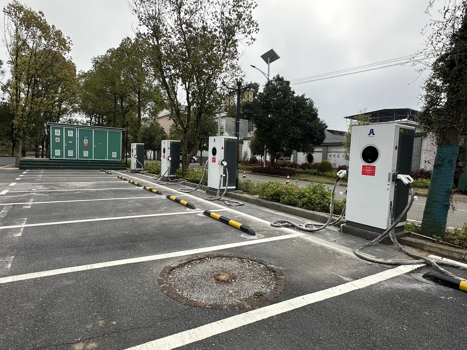
That distinction matters. A photograph is good evidence of cabinet placement, vehicle space and upstream equipment. It is not an uptime report or a power log.
Freeze 5: define digital operation end to end
The vehicle connection and the backend connection are different interfaces.
- Vehicle-side communication helps the EV and charger establish and control a charging session.
- OCPP is used between a charging station and a charging management system. The Open Charge Alliance publishes OCPP and distinguishes its versions.
“OCPP supported” is therefore only the beginning of a specification. Freeze:
- exact OCPP version and required functions;
- certification status, if certification is required;
- target CSMS and integration owner;
- security and credential-provisioning scope;
- Ethernet, cellular or Wi-Fi connectivity and signal responsibility;
- behavior during network loss and recovery;
- RFID, app, account, QR or payment-terminal workflow;
- tariff, tax, receipt and roaming requirements where applicable;
- session-record fields and ownership of operational data;
- remote access permissions and audit boundaries;
- alarms, help contact, first response and escalation;
- firmware approval, deployment and rollback responsibility.
Turn these requirements into end-to-end tests. A successful RFID read does not prove that the CSMS stored the correct energy and tariff data. A successful OCPP connection does not prove that a payment reversal, remote reset or interrupted-session recovery works.
Freeze 6: move from FAT to SAT and handover
Commissioning should not be reduced to “the screen switched on.” Use four evidence stages.
1. Technical submittal approval
Before production or shipment, approve the exact model/configuration schedule, drawings, option list, manuals, communication scope, conformity-document plan, FAT plan and project exclusions.
2. Factory acceptance testing (FAT)
FAT verifies the agreed equipment scope before shipment. The project team should define which inspection, functional, communication and simulated-load cases are practical at the factory, who witnesses them, and what record is produced. FAT cannot prove site wiring, field communications quality or interoperability with every vehicle.
3. Readiness to energise
Qualified project parties confirm that the installed civil and electrical works, protective measures, labels, earthing/grounding, access controls and inspections satisfy the approved destination design. The manufacturer’s checklist does not replace local electrical inspection or authority requirements.
4. Site acceptance testing (SAT) and handover
The SAT plan should identify:
| Test field | What the plan must state |
|---|---|
| Test case | Exact action or operating scenario |
| Preconditions | Vehicle, load, network, account and site state required |
| Expected result | Measurable pass condition, not “works normally” |
| Evidence | Photo, meter reading, charger log, CSMS record or signed inspection |
| Witness/owner | Who performs, witnesses and accepts the result |
| Failure rule | Punch-list owner, corrective action and retest requirement |
Depending on project scope, SAT cases may include:
- installed-equipment and label inspection;
- emergency-stop and safe shutdown/recovery behavior;
- single-vehicle charging with an approved test vehicle;
- simultaneous sessions and the agreed allocation rule;
- operation at the configured site power limit;
- authentication and payment paths;
- matching charger and CSMS session records;
- network interruption and recovery;
- alarms, remote diagnostics and escalation;
- user and maintenance training;
- delivery of as-built drawings, backups, manuals, spare parts and contacts.
Electrical safety and protection tests must be specified and performed by qualified parties under the approved local design. The article cannot prescribe universal test voltages or pass values.
Final payment and warranty start should refer to defined commercial milestones. Do not leave “delivery,” “installation complete,” “energised,” “SAT passed” and “handover accepted” as interchangeable phrases.
Eight project symptoms that reveal an interface gap
| Symptom | Likely interface failure | Verify first | Required deliverable |
|---|---|---|---|
| Utility energisation delays the station | Equipment order preceded utility feasibility | Utility application, point of connection and upgrade scope | Approved power plan and dependency schedule |
| Site trips when several ports operate | Concurrency was not included in load/protection design | Site limit, allocation settings, one-line and event logs | Coordinated load and protection design plus retest |
| Vehicle receives less power than expected | Vehicle, voltage, current or SOC ceiling was ignored | Vehicle request, charger output log and per-port limits | Vehicle-output compatibility matrix |
| Cable cannot reach an inlet safely | Layout used cabinet footprint, not vehicle/inlet geometry | As-built bay dimensions, cable origin and target vehicles | Vehicle swept-path and cable-reach drawing |
| Charger starts but transaction data is wrong | Hardware and CSMS teams tested different boundaries | Charger/CSMS timestamps, meter values, tariff and session IDs | End-to-end interface test report |
| Station does not recover after network loss | Offline/reconnect behavior was not specified | Router/SIM status, charger queue and CSMS logs | Network-loss and recovery test case |
| Certificate does not match the delivered variant | Portfolio-level evidence was substituted for model evidence | Model plate, BOM/options, certificate annex and report | Destination document matrix tied to serial/model records |
| Faults remain open after handover | Support ownership and escalation were never assigned | Warranty boundary, contact tree, remote-access rights and spares | Signed operating responsibility and escalation matrix |
These are diagnostic starting points, not remote fault conclusions. Electrical work and troubleshooting remain the responsibility of qualified project personnel.
Copyable Station Design Freeze Pack
Send the following information before requesting a final station configuration.
Project and operating basis
- Destination country and installation address or climate zone.
- Public, fleet, depot, dealer, workplace or mixed-use operation.
- Vehicle models/classes, quantity and inlet position.
- Connector/inlet types.
- Battery voltage and maximum accepted DC power/current where available.
- Arrivals by hour or shift.
- Energy required per session and turnaround/dwell window.
- Normal and peak simultaneous sessions.
- Growth or expansion scenario.
Electrical and civil basis
- Grid voltage/frequency and utility contact/status.
- Available capacity and other site loads.
- Transformer, switchboard and meter information.
- Current site survey, one-line and layout, if available.
- Approximate feeder/trench route and distance.
- Parking geometry, vehicle movement and accessibility requirements.
- Environmental, drainage, impact-protection and service-access constraints.
Charging and digital basis
- Desired ports and preliminary power range.
- Required single-session and simultaneous behavior.
- Connector/cable length and cable-management needs.
- CSMS provider, OCPP version and required functions.
- Authentication, payment, receipt and roaming requirements.
- Network method, data ownership and remote-support rules.
Evidence and delivery basis
- Destination conformity, tender and utility document requirements.
- Required FAT/SAT witness points and test vehicles.
- Training, spares, warranty and support expectations.
- Quantity, delivery phases and required commissioning date.
HG Power can review this pack against its 40–480 kW DC portfolio and identify questions that must be closed before a model/configuration is frozen. The review does not replace local engineering, code review, permitting, utility approval or licensed installation.
Frequently asked questions
How much power should a DC fast charger station have?
Size from the energy required during each operating window, the arrival pattern, maximum dwell, simultaneous sessions, vehicle voltage/current acceptance and the site’s available power. Do not size only from the fastest vehicle or the largest available cabinet.
How many charging ports should the station install?
Port count depends on concurrent demand, queue tolerance, parking turnover, redundancy and expansion plans. Modelling the arrival distribution is more useful than dividing a daily vehicle total by operating hours. NLR’s EVI-LOCATE identifies desired port count/power and existing transformer/service assets as useful starting inputs.
Can two vehicles receive full charger power at the same time?
Only if the exact configuration and site supply support that behavior. Confirm total cabinet output, maximum per connector, module allocation, site limit and the two-vehicle SAT case. Two connectors do not prove two full-power ports.
What electrical supply does a DC fast charging station require?
It depends on the quoted equipment, destination grid, total station power, local design and other site loads. Ask the project’s utility and qualified electrical designer to approve the site-specific input and one-line; do not copy a voltage or breaker from an unrelated datasheet.
Is OCPP support enough to connect to any CSMS?
No. Specify the OCPP version, required features, security, certification requirement and target backend, then run agreed end-to-end cases. OCPP also does not prove vehicle-connector compatibility or payment-terminal behavior.
What is the difference between FAT and SAT?
FAT verifies the agreed equipment scope under factory conditions before shipment. SAT verifies the installed system and its site interfaces. Neither replaces the other, and neither replaces destination electrical inspection.
Which documents should be delivered at handover?
The project-specific list may include approved/as-built drawings, model and serial schedule, manuals, settings backups, inspection and test records, FAT/SAT reports, conformity documents tied to the delivered variants, training record, spare-parts list, warranty terms and support/escalation contacts.
When should a project choose AC charging or a phased build?
Consider it when vehicles have long dwell times, fast turnaround is not required, initial demand is uncertain or site capacity is limited. A mixed AC/DC design or reserved expansion infrastructure can be better than installing maximum DC power immediately.
Turn a charger enquiry into a station specification
The most useful first message is not “Please quote four 240 kW chargers.” It is a short design basis showing the destination, vehicles, operating window, concurrent sessions, site power, layout and digital workflow.
Send HG Power the Station Design Freeze Pack above to request a project-specific review of the 40–480 kW DC charging portfolio. The response can identify an appropriate equipment family, missing site inputs and the documentation that should be confirmed before order.
For the wider procurement sequence, use the Commercial EV Charger Buyer’s Guide. For project-specific discussion, contact HG Power.
Прокси-сервер и VPN — это способы, применяемые для сокрытия реального сетевого адреса пользователя.
Данные сервисы гарантируют конфиденциальность в сети и оберегают персональную информацию от посторонних.
Основное отличие между заключается в что прокси работает на уровне отдельных приложений, а туннель — шифрует полностью сетевой поток.
Соответственно, данная технология лучше применяется для обхода ограничений ресурсов, а второе решение — для всесторонней защиты и гарантии полной анонимности.
https://proxyvpn.uk/
The proxy gateway serves as a kind of intermediary connecting an end user and online resources.
When a user connects via the proxy, their requests go to the server first, and after that the service relays your data to the intended website for you.
Encryption DNS over HTTPS How DoH works, what it protects, when to enable it and when not to, browser vs system DoH, and DoH compared with DoT. Read the article
This approach can mask your IP address, overcome geoblocking, and strengthen privacy.
That said, some proxy services are insecure, so you should choose a credible service.
The proxy acts as a type of service connecting your device and online resources.
When a user connects via the proxy, their traffic go through the intermediary initially, and subsequently it forwards them to the intended website in your place.
VPN WireGuard setup Install the server, generate keys, add peers and connect your first device.
Using a proxy can mask your real IP address, overcome regional blocks, and enhance online safety.
That said, some proxy servers are unreliable, so you should pick a reputable service.