
Split vs All-in-One DC Charger: How to Choose by Site, Grid and Fault Risk
Both designs deliver DC fast charging. They differ in where AC becomes DC, which outputs share the power and how many bays one fault can stop. Compare quotes on those three boundaries, not on the biggest kW figure.
By HG Power. Published 9 November 2026. Technical review: Marvin Zhou.
Choose an all-in-one DC charger when a site needs a few fast-charging bays, has room for a full cabinet beside them and values the simplest installation. Choose a split DC system when many bays share one power budget, dispensers must stay slim, or a megawatt site can connect at medium voltage. At low voltage, the architecture alone does not shrink the grid connection.
This guide is for charge point operators, fleet depot teams, EPC contractors and distributors comparing quotations. “Split” here means an EV charging system with a separate power cabinet and vehicle-side dispensers. It is not the dual-battery “split charger” used in camper vans.
Split vs all-in-one at a glance
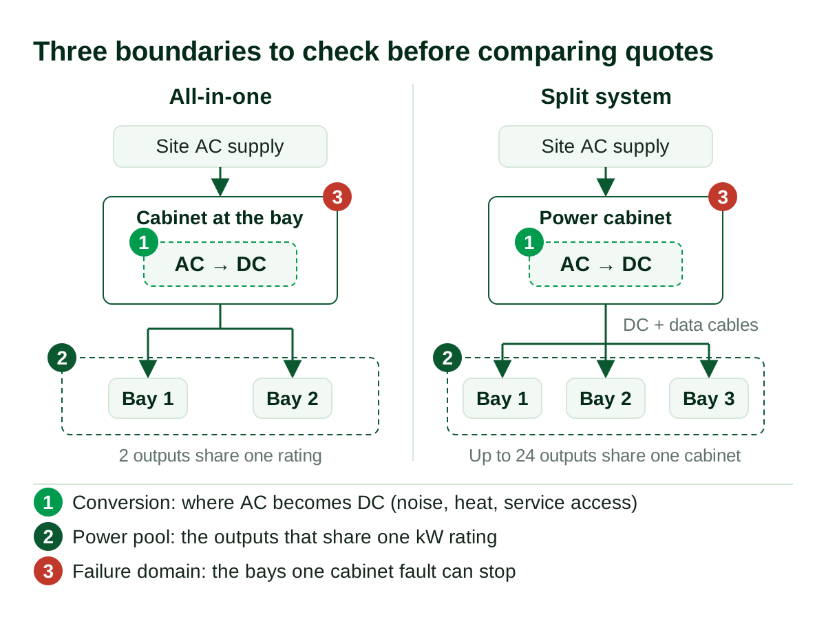
An all-in-one (integrated) DC charger keeps AC-to-DC conversion, control and the charging cables in one cabinet at the bay. A split DC system puts the conversion equipment in a power cabinet and sends DC to slimmer dispensers at the bays.
| Decision point | All-in-one DC charger | Split DC system | What goes wrong if you skip it |
|---|---|---|---|
| Where AC becomes DC | Inside the cabinet at the bay | In a power cabinet away from the bays | Noise, heat and service access end up beside drivers, or the cabinet has nowhere to go |
| Space at the bay | A full cabinet. HG Power’s Genesis 360 kW unit measures 2,050 × 830 × 830 mm | A dispenser. The HG Power 360 kW split dispenser base is 430 × 201 mm | Bays become too tight for parking and cable reach |
| Who shares the power | The unit’s own outputs (two on the Genesis series) | Every dispenser on the cabinet (10–24 outputs on the Aurora series) | Simultaneous power per vehicle is lower than the brochure suggests |
| Grid demand at low voltage | Set by installed kW and any site power limit | The same | The utility application is sized on a false saving |
| Civil works | One location per unit | Cabinet pad plus DC and communication routes to every dispenser | Trenching appears after the equipment price is agreed |
| Expansion | Add another complete unit | Add dispensers or modules within the cabinet’s supported limit | A cabinet is full before phase two |
| One fault takes out | That unit’s outputs | One dispenser, or every dispenser if the shared cabinet fails | Uptime targets are missed at busy hours |
| HG Power power range | Genesis 40–480 kW | Aurora 240 kW–2.6 MW; 10 kV direct mount 2.6 MW | The wrong product family is quoted |
The footprint figures come from two specific HG Power documents: the CCS2 Genesis 360 kW specification and the CCS1 360 kW split charger manual. On those models, a dispenser takes roughly one-eighth of the floor area of the integrated cabinet. Other models differ.
The Three-Boundary Test
Most quotations compare the largest kW figure on each brochure. That number hides the three things that decide whether a design works on your site. Ask each supplier to state all three boundaries in writing.
1. The conversion boundary: where does AC become DC?
This boundary sets where noise, heat, ventilation and service access sit. In an all-in-one unit, they sit at the bay. In a split system they sit at the power cabinet, which can go to a plant area, behind a building or beside the transformer.
Moving the conversion equipment does not remove it. HG Power’s 360 kW split manual recommends a 1,300 × 800 mm foundation at least 200 mm high for the power cabinet and a crane for installation. The dispenser needs a 510 × 280 mm foundation and is placed by forklift. Both need a home on the site drawing.
Ask: Where will each cabinet stand, what clearances does it need, and how will it be lifted into place?
2. The power-pool boundary: which outputs share which kilowatts?
This boundary decides what each vehicle actually receives when several are plugged in. A Genesis all-in-one charger shares its rating between two outputs. An Aurora split cabinet shares its rating across 10 to 24 outputs.
Adding a dispenser adds a place to plug in. It does not add power. A 360 kW cabinet with six outputs still has 360 kW to divide.
Ask: What power is available per vehicle when one, half and all bays are occupied?
3. The failure-domain boundary: what does one fault take offline?
This boundary decides how many bays stop when one part fails. A fault inside one all-in-one unit normally affects only that unit’s outputs. A dispenser fault in a split system affects that dispenser. A fault in the shared power cabinet’s control or input can affect every dispenser it feeds.
Ask: For a dispenser, a power module, the cabinet controller and the cabinet’s incoming supply, how many outputs remain usable and at what power?
Does a split DC charger reduce the transformer size?
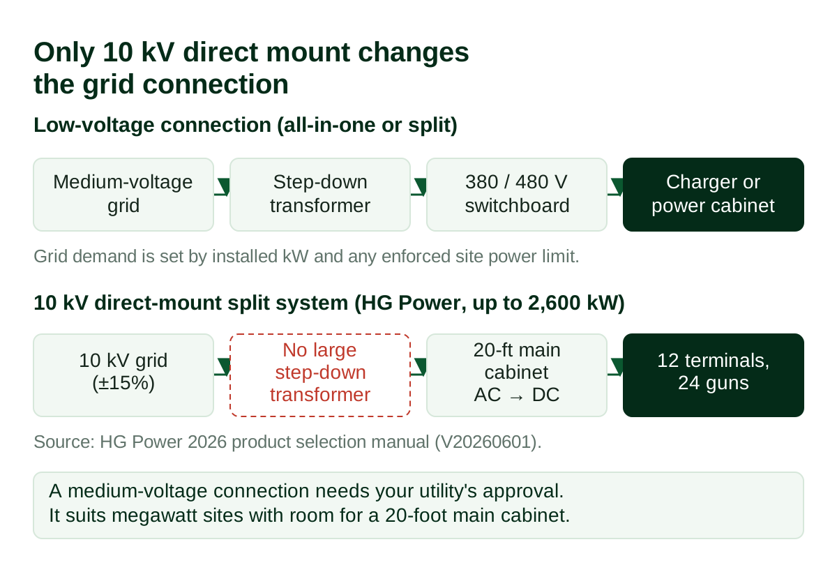
Not by itself. At low voltage, a split charger needs the same grid connection as all-in-one chargers with the same installed kW and the same site power limit. A smaller transformer comes from installing less simultaneous power or enforcing a power ceiling. The exception is a medium-voltage direct-mount split system, which connects at 10 kV without a large step-down transformer.
Same kW, same input current
HG Power’s own specifications show why. At 380 V three-phase, the CCS2 Genesis 120 kW charger is rated at 194 A input current. The Genesis 360 kW is rated at 582 A. Three times the power draws three times the current.
Putting that 360 kW of conversion into a split power cabinet does not change the physics. Both documents list about 95% efficiency at nominal output, so the losses are similar too. The utility sees the installed conversion capacity and how it is controlled. It does not care which enclosure holds it.
What actually reduces grid demand
Two things reduce the connection you need:
- Installing less simultaneous power. Eight dispensers on a 600 kW cabinet draw less than eight 150 kW chargers, because the design provides half the simultaneous output. Check that the lower output still meets your charging windows.
- Enforcing a site power ceiling. The US Department of Energy lists an enforced power ceiling across multiple chargers as a way to reduce the need for upgraded equipment. Load management of this kind works with both architectures.
For transformer sizing method and worked examples, see our EV charging transformer sizing guide.
The exception: 10 kV direct-mount split systems
There is one case where the architecture changes the grid connection. HG Power’s high-voltage direct-mount split charger takes a 10 kV ±15% medium-voltage supply and delivers up to 2,600 kW. Our 2026 product selection manual describes it as a direct 10 kV grid connection with no large transformer.
That route only fits megawatt sites: the main cabinet is a 20-foot unit feeding 12 terminals and 24 charging guns, and the manual lists 97% efficiency. It also depends on your utility allowing a medium-voltage connection of this kind. Confirm that with the utility before treating it as an option.
How is power shared between dispensers?
One split power cabinet can feed many outputs. HG Power’s Aurora series supports 10 to 24, and its 360 kW CCS1 split manual lists three or six terminals with one or two outputs each. All outputs share the cabinet’s rating. Each output is also capped by its own current limit and by what the vehicle accepts, so check per-vehicle power with every bay occupied.
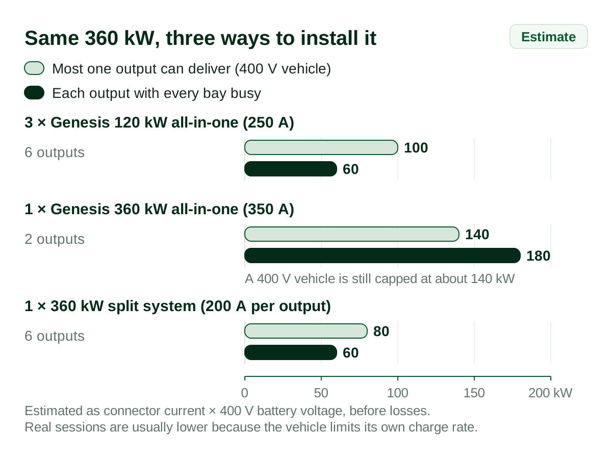
The same 360 kW, three ways
The table compares three ways to install 360 kW, using the current limits in HG Power’s documents. Power per output is estimated as connector current × vehicle battery voltage, before losses. Real sessions are usually lower because the vehicle limits its own charge rate.
| Configuration | Outputs | Most one output can deliver | If every output is in use (equal split) |
|---|---|---|---|
| Three Genesis 120 kW all-in-one chargers (250 A per connector) | 6 | About 100 kW to a 400 V vehicle; 120 kW to an 800 V vehicle | About 60 kW each |
| One Genesis 360 kW all-in-one charger (350 A per connector) | 2 | About 140 kW to a 400 V vehicle; about 280 kW to an 800 V vehicle | Up to 180 kW each; a 400 V vehicle is still capped at about 140 kW |
| One 360 kW CCS1 split system with six outputs (200 A per output) | 6 | About 80 kW to a 400 V vehicle; 150 kW at the 750 V output maximum | About 60 kW each |
Three lessons follow:
- Connector current matters as much as cabinet kW. A 400 V vehicle on a 200 A output cannot draw more than about 80 kW, however large the cabinet.
- Pooling helps when demand is uneven. If vehicles arrive at different times or sit near full charge, a shared pool can move power to the vehicle that needs it. Ask whether allocation is dynamic or fixed.
- Pooling does not create power. With all six bays busy, both the three-charger design and the split design give about 60 kW per vehicle.
For two-output allocation on all-in-one units, see how dual-gun DC chargers allocate power.
Footprint, civil works and cable routes
The physical layout often decides the choice before the electrical design does.
| Item | All-in-one (Genesis 360 kW, CCS2) | Split (360 kW, CCS1 manual) |
|---|---|---|
| Unit at the bay | 2,050 × 830 × 830 mm cabinet | 430 × 201 mm dispenser |
| Foundation at the bay | Ground mounting; size per site design | 510 × 280 mm, at least 200 mm high |
| Separate cabinet | None | 1,200 × 750 mm; 1,300 × 800 mm foundation, at least 200 mm high |
| Installation equipment | Per site plan | Forklift for dispensers; crane for the cabinet |
| Cable entry | Per site plan | Bottom entry; 900 mm cable reserve at the dispenser, 600 mm at the cabinet |
| Charging cable | 5 m | Per terminal configuration |
The hidden cost of a split system is the route between the cabinet and each dispenser: DC power cables, communication cables, ducts, trenching and pavement reinstatement. Maximum cabinet-to-dispenser distance depends on the model and cable design, so get it in writing from the supplier. Our manuals do not give a universal figure, and you should not accept one without the cable sizing behind it.
The hidden cost of an all-in-one design is space. Every unit needs its full cabinet, service clearance and vehicle protection beside the bay. On narrow urban sites that can cost parking spaces.
The split cabinet’s incoming supply is heavy. HG Power’s 360 kW split manual specifies an input cable of at least 2 × 3 × 150 mm² plus 2 × 70 mm². Your electrical designer must confirm the final size for your local code, cable route and installation method.
Failure domain and maintenance
No architecture guarantees uninterrupted charging. The question is how many bays a single fault removes and how quickly the faulty part can be replaced.
| Fault | Several all-in-one units | One split system |
|---|---|---|
| One charging cable or connector | That output | That output |
| One power module | That unit charges at reduced power, if the design allows | The pool loses that module’s share |
| One dispenser or unit controller | That unit’s outputs | That dispenser’s outputs |
| Shared cabinet controller or incoming supply | Not shared; only that unit | Every dispenser on that cabinet |
| Site main supply | Whole site | Whole site |
HG Power’s 360 kW split charger uses hot-pluggable power modules, which shortens module replacement. That does not remove the shared-cabinet risk. A large site can split its bays across two or more cabinets so one cabinet fault never stops every bay.
Uptime is not just an operator preference. For federally funded US sites, the Joint Office of Energy and Transportation describes a 97% uptime minimum. A design that loses ten bays on one fault makes that target harder to hit.
Ask the supplier: Is there N+1 module redundancy? What spare parts are recommended on site? What is the replacement procedure for a module, a dispenser and the cabinet controller?
Which architecture fits your site?
| Site situation | Usually start with | When not to |
|---|---|---|
| Hotel, retail or office adding 1–2 fast-charging bays | All-in-one | When bays are tight and a plant area is close by |
| Highway or urban hub with 8+ bays and uneven arrivals | Split | When every bay must deliver high power at the same time; compare at equal simultaneous output |
| Bus or logistics depot charging overnight | Split, sized on departure times | When parking zones are far apart; several all-in-one units may avoid long cable routes |
| Heavy-truck hub at megawatt scale | Aurora 960 kW–2.6 MW split, or 10 kV direct mount where the utility allows | When the site cannot host a 20-foot main cabinet or the utility refuses a medium-voltage connection |
| Narrow urban kerbside or car park | Split, with the cabinet in a plant room | When there is no protected place for the cabinet |
| Constrained grid connection | Either, with an enforced site power limit | Do not choose split on the assumption that it lowers demand by itself |
| Phased rollout across separate areas | All-in-one | When phase two will add many bays in one area that a cabinet could serve |
| No equipment room or cabinet pad possible | All-in-one | — |
Five project killers to check before you sign
| Symptom | Root cause | How to verify | How to avoid |
|---|---|---|---|
| Two quotes show the same kW but vehicles charge at very different speeds | Power-pool and connector limits not stated | Ask for per-vehicle power at 1, half and all bays occupied | Make simultaneous output a contract figure |
| Trenching cost appears after the equipment order | Cabinet-to-dispenser route not in scope | Mark every route on the site drawing | Price cables, ducts, trenching and reinstatement in the same quote |
| Utility rejects the connection application | Split assumed to reduce demand | Recalculate from installed kW and the enforced site limit | Size the grid connection on real simultaneous demand |
| One fault closes the whole site at peak time | All bays on one shared cabinet | Ask for the fault table above | Split large sites across more than one cabinet |
| Equipment arrives with the wrong input voltage | Market configuration not specified | Check the quoted input voltage against your supply | Specify voltage, frequency, connector and certificates per model |
The last point is real in our own documents. Our CCS1 360 kW split manual lists a 380 V three-phase input, while the Aurora range lists both 380 V and 480 V options. Always state your supply voltage when you request a quotation.
HG Power options for both architectures
We build both. The figures below come from our 2026 product selection manual and model specifications. Connector, voltage and certificate details vary by model, so confirm them for the exact configuration you are quoted.
All-in-one
- Genesis integrated DC chargers, 40–480 kW in three frame sizes: 40–80 kW, 120–180 kW and 200–480 kW. All have two outputs, DC 200–1,000 V and IP54. The CCS2 Genesis 120 kW and 360 kW specifications list CE, RED, CB and TUV marks, plus the EN IEC 61851-1, EN 61851-23 and EN 61851-24 standards. Those marks are documented for those two CCS2 models only.
Split
- Aurora separated-type DC charging station, 240–960 kW, 10–24 outputs, air-cooled main cabinet, 200/250 A outputs and 600 A liquid-cooled outputs.
- Aurora split DC charging, 960 kW–2.6 MW, 400 A outputs and 1,000 A liquid-cooled outputs for CCS1, CCS2 and GB/T.
- Deepsea all-liquid-cooled split charger, 600–2,000 kW.
- 10 kV direct-mount split charger, 2,600 kW, 12 terminals, 24 guns.
Across these families, outputs can be configured for CCS1, NACS, CCS2, CHAdeMO or GB/T, with OCPP 1.6 or 2.0.1 available as an option. If you are deciding cooling as well, read liquid-cooled vs air-cooled DC fast chargers. For power class, see 120 kW vs 240 kW vs 480 kW DC chargers.
Standards note: split systems have their own annex
The DC charging standard IEC 61851-23 was revised in 2023. The new edition added an annex for “multi- side B separated EV supply equipment” (Annex FF): equipment in which one supply unit feeds several separated vehicle-side outputs. Ask a split-system supplier how its design and test reports address this edition. Then check what your market’s authority requires on top of it.
Supplier checklist for a split DC system
Send these questions with your request for quotation:
- Installed AC/DC conversion capacity and total DC output, stated separately, plus the number of outputs and each output’s continuous and boost current (with boost duration).
- Power per vehicle with one, half and all outputs in use, and whether allocation is dynamic or fixed.
- Maximum cabinet-to-dispenser cable distance, with cable sizes for your layout.
- Cabinet and dispenser dimensions, foundations, clearances and lifting method.
- Input voltage, frequency, input current and recommended input cable.
- Which outputs stay live after a dispenser, module, controller or input fault.
- Module redundancy, recommended spare parts and replacement time.
- Connector types, communication protocol (OCPP version) and backend integration.
- Certificates and test reports for the exact model and your market, including the IEC 61851-23 edition.
- What the price includes: commissioning, cables between cabinet and dispensers, and remote support.
Questions buyers ask
What is the difference between a split DC charger and an all-in-one DC charger?
An all-in-one DC charger keeps power conversion, control and charging cables in one cabinet at the bay. A split DC charger moves the conversion equipment into a separate power cabinet that feeds slimmer dispensers. Both deliver DC fast charging. What differs is equipment location, how many outputs share the power, and how many bays one fault affects.
Is a split DC charging system cheaper than several all-in-one chargers?
Sometimes, but not because of the split layout itself. Savings usually come from installing less simultaneous power and sharing it across bays. The cabinet-to-dispenser cables, ducts and trenching can cancel that saving. Compare complete installed quotes that deliver the same power per vehicle with every bay occupied, not equipment prices alone.
Does a split DC charger reduce the transformer size I need?
Not at low voltage. A split charger with the same installed kW and site power limit needs the same grid connection as all-in-one units. HG Power’s 360 kW integrated charger draws 582 A at 380 V. A split cabinet of the same rating draws about the same. A medium-voltage 10 kV direct-mount split system is the exception.
How many dispensers can one power cabinet serve?
It depends on the model. HG Power’s Aurora split cabinets support 10 to 24 outputs, and its 360 kW CCS1 split system uses three or six terminals. Every output shares the cabinet’s total rating. With all bays busy, each vehicle gets a fraction of that rating. Its output current limit and battery voltage cap it further.
What should I ask a Chinese manufacturer before ordering a split DC system?
Ask for installed conversion capacity versus advertised output, continuous and boost current per connector, and power per vehicle with one, half and all bays occupied. Ask for the maximum cabinet-to-dispenser distance, which outputs survive a cabinet fault, and certificates for the exact model and market. Get every answer in writing.
Can both architectures charge Tesla or NACS vehicles?
Yes, if the outputs are ordered with NACS connectors. HG Power lists NACS as an output option on both the Genesis all-in-one and Aurora split families, alongside CCS1, CCS2, CHAdeMO and GB/T. Confirm the connector and protocol for each output in the quotation.
Is a dual-gun DC charger the same as a split charger?
No. Dual-gun means one unit has two charging connectors. Split means the power cabinet and the dispensers are separate. A Genesis all-in-one charger has two guns in one cabinet. A split system can feed many single- or dual-output dispensers from one cabinet.
About this guide
HG Power (Shenzhen Hongjiali New Energy) has designed and manufactured EV charging equipment since 2016. The company has 200+ employees, including 100+ engineers, and holds 100+ patents. We build both integrated and split DC chargers, so this guide does not favour one architecture. The right answer depends on your site.
Reviewed by: Marvin Zhou
Sources
- HG Power, 2026 Product Selection Manual, V20260601: Genesis, Aurora, Deepsea and 10 kV direct-mount specifications.
- HG Power, CCS1 360 kW DC Charger User Manual (split type), model ANSI-DCF360F.
- HG Power, CCS2 Genesis 120 kW and 360 kW Charger Specifications.
- IEC, IEC 61851-23:2023, DC EV supply equipment.
- US Department of Energy, FEMP, Managed EV Charging for Federal Fleets.
- Joint Office of Energy and Transportation, Ensuring a Reliable Charging Experience (webinar text).
Get both layouts priced for your site
Send us your site drawing and we will propose an all-in-one layout and a split layout side by side. Each proposal covers equipment positions, simultaneous power per vehicle and installation scope. Include:
- Country and supply voltage (low voltage, or 10 kV if available)
- Available grid capacity in kVA
- Vehicle types, battery voltage class (400 V or 800 V) and connector standard
- Number of vehicles per day and typical parking time
- Bays in phase one and bays planned later
- Where a power cabinet could stand
Related reading: Dual-gun power allocation · Transformer sizing for EV charging · OCPP 2.0.1 vs 1.6 procurement guide · Fleet EV charging · EV charger OEM/ODM