
Engineering guide · Updated August 2026
Solar EV Charging Station Design: Match PV, Storage, Grid and Charging Demand
A decision-first guide to solar contribution, managed charging, storage, grid limits and project verification.
Direct answer: A commercial solar EV charging station should be sized from time-series data, not by matching solar-panel nameplate power to charger nameplate power. Define the vehicle schedule, solar production profile, grid/site limits and battery dispatch first. Then test both energy demand in kWh and peak power in kW before selecting chargers, storage or the electrical architecture.
Solar can contribute to workplace, fleet, public and remote charging. But “solar powered” is not a complete specification. A station may use solar directly at midday, shift it through a battery, blend it with the grid, or reserve it for selected loads. Each design has a different cost, control strategy and proof burden.
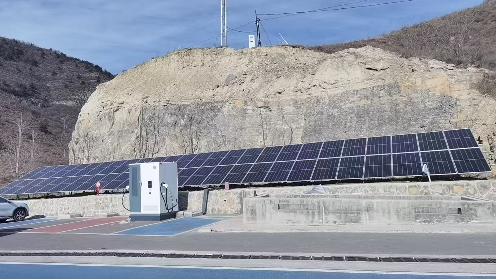
The terms solar EV charger and solar-powered EV charger are often used for the same project idea. In commercial design, however, the boundary normally includes the PV system, charging equipment, grid interface, optional storage and the controls that coordinate them.
This guide is for project owners, EPCs, distributors and procurement teams who need a defensible system brief—not a generic panel count or an unsupported payback promise.
The first decision is not the charger model. It is the operating objective: which vehicles must receive how much energy, by what departure time, under which grid and solar conditions?
Start with the Four-Clock Test
A workable solar EV charging station aligns four clocks. If one is missing, the bill of materials may look complete while the operating plan is not.
1. What does the vehicle clock require?
Record each vehicle class, inlet/connector, arrival window, departure deadline, starting state of charge or energy deficit, target energy, maximum charge acceptance and priority. For public sites, use observed or forecast arrival distributions rather than a single “average vehicle.” For a fleet, use route and dwell records.
This clock defines the service promise. A 120 kW charger does not mean every connected vehicle will accept 120 kW, and a large annual energy forecast does not reveal a 20-minute concurrency peak.
2. When does the solar clock produce?
Use a location-specific PV production profile that accounts for season, array orientation, temperature, shading and system losses. NREL's PVWatts can provide an early grid-connected estimate for many locations, but detailed engineering still requires site and shading review.
Annual PV energy is not enough. Two sites can produce the same annual kWh and have very different coincidence with charging demand.
3. What does the grid clock allow and charge for?
Document the site's existing load, available connection capacity, import and export limits, transformer and switchgear constraints, interval tariff, demand-charge method and upgrade timeline. Engage the utility or responsible electrical authority before the equipment design is frozen.
The grid clock may change by hour, season or operating condition. A site with adequate annual energy supply can still violate a 15-minute demand limit.
4. What job does the storage clock perform?
If a battery is proposed, define usable energy, charge/discharge power, SOC limits, reserve, efficiency, degradation assumptions and dispatch priority. “Add a battery” is not a control strategy.
A battery used to absorb midday PV has a different dispatch duty from one used to cap grid import, bridge a delayed grid upgrade or support selected loads during an outage. Combining objectives can be possible, but the model must show which objective has priority when they conflict.
The Four-Clock Test
All four profiles must share the same interval and scenario boundary. Annual totals cannot show a short concurrency peak.
Keep two ledgers: energy in kWh and power in kW
Many feasibility errors begin by mixing energy and power.
- Energy (kWh) answers: how much electricity must move during a day, shift or charging session?
- Power (kW) answers: how quickly must it move at a particular moment, and which component sets the limit?
For an initial energy ledger:
Required EV energy = sum of the energy required by all planned sessions
For the site power ledger at each time step:
Grid exchange = EV load + other site load + battery charging − PV output − battery discharging
With this sign convention, a positive result is grid import and a negative result is export. The final model must also include conversion losses, auxiliary loads and operational reserves. Keep the sign convention consistent so every party can reproduce the result.
A hypothetical example—not a product recommendation
Suppose six fleet vehicles each need 45 kWh before departure. The charging-energy requirement is 270 kWh before losses. That still does not define the PV array, charger power or battery size.
If the vehicles dwell from 09:00 to 17:00, charging can potentially follow daytime production. If four arrive at 17:00 and must leave at 18:00, the same 270 kWh energy ledger creates a much harder power problem. Vehicle acceptance, available ports, output allocation and the site cap determine the actual peak; simply multiplying four ports by a charger label is not a valid load study.
The correct question is: what charging schedule meets every departure target while staying inside the site and equipment limits across the required solar and traffic scenarios?
Choose a rung on the Solar Contribution Ladder
“Solar EV charging” covers several different systems. Choose the lowest rung that satisfies the operating objective; add complexity only when the data supports it.
| Rung | Configuration | Best fit | Evidence required | Stop here when… |
|---|---|---|---|---|
| 1 | Grid-connected EV charging with coincident PV | Existing PV or a planned canopy and meaningful daytime charging | Interval EV load, interval PV estimate, site load and import/export limits | Direct coincidence provides the intended solar contribution and grid peaks are acceptable |
| 2 | PV + grid + managed charging | Vehicles have flexible dwell or dispatch priority | Rung 1 data plus departure deadlines, charging priorities and control interface | Scheduling meets service targets without stationary storage |
| 3 | PV + battery + grid | Solar must be shifted, a grid peak capped or a defined constraint bridged | Battery power/energy model, SOC rules, tariff, degradation and interconnection review | Modeled value and service improvement justify storage complexity |
| 4 | Constrained-grid or island-capable system | Remote sites, explicit resilience duty or protected-load operation | Seasonal low-sun study, islanding/protection design, reserve policy, black-start/transition logic and failure scenarios | Never select this rung from a marketing claim alone |
The Solar Contribution Ladder
Choose the lowest rung that satisfies the operating objective. Every added function creates a new proof requirement.
When is managed charging the better first move?
Managed charging deserves evaluation before stationary storage when vehicles remain parked longer than the energy transfer requires. It can move sessions toward solar production or keep aggregated charging under a site limit—provided the departure commitments and control interfaces are known.
The 2026 IEA PVPS Task 17 report shows why this is site-specific: workplace charging can align well with daytime solar, while different vehicle and bus strategies create different infrastructure and grid trade-offs. Its case-study percentages should not be copied into a commercial proposal; the underlying principle is to model the local schedule.
Does a solar EV charging station need battery storage?
Not automatically. Storage is justified by a defined problem and a measured improvement.
Storage may be useful when it can:
- shift midday PV to a later charging window;
- cap grid import during simultaneous sessions;
- absorb PV that would otherwise be curtailed under an export limit;
- bridge a temporary or permanent site-capacity constraint;
- support a separately engineered resilience objective;
- stabilize a defined DC bus or microgrid operating strategy.
Do not add storage yet when:
- vehicles can already charge during solar production;
- the grid limit comfortably supports the modeled peak;
- the tariff does not reward the proposed dispatch;
- a larger battery is being used to hide an undefined vehicle schedule;
- required space, fire-safety treatment, protection or interconnection is unresolved;
- the model omits degradation, losses, replacement and auxiliary consumption;
- the project has no written rule for dispatch priority.
Battery power sets how fast the system can charge or discharge. Usable battery energy sets how long it can sustain that action. A 125 kW PCS and a 261 kWh nominal battery, for example, are not interchangeable descriptions and do not by themselves establish usable duration.
Can storage make the station work during an outage?
Only if outage operation is explicitly designed. The project needs an islanding boundary, compatible protection and switching, a protected-load list, reserve policy, transition/black-start logic where applicable, and an operating plan for low-sun periods. A battery beside a charger is not proof of backup operation.
AC-coupled or DC-coupled solar charging?
There is no universal winner. The U.S. DOE's charging-station site-design guidance identifies different equipment, protection, controllability and workforce trade-offs for AC and DC architectures.
| Decision factor | AC-coupled approach | DC-coupled / common-DC-bus approach |
|---|---|---|
| Retrofit fit | Often easier when PV, storage or chargers already have AC interfaces | Often stronger as an integrated new-build study |
| Conversion path | May include more separate AC/DC stages | May centralize or reduce some conversion stages, depending on topology |
| Equipment ecosystem | Broad commercial availability and familiar installation practices | Supplier-specific converters, controls and protection may be more important |
| Controls | Assets can retain independent controls; coordination still matters | Energy management and DC-bus coordination are central design functions |
| Protection | Familiar AC distribution does not remove EV/PV/BESS protection duties | DC protection, isolation, fault handling and bus limits require explicit engineering |
| Failure domains | An asset may be isolated more independently, topology permitting | Shared buses/controllers can create common interfaces that need failure analysis |
| Expansion | Check switchgear, transformer, AC bus and communications | Check DC bus, converter, protection, voltage ranges and vendor interoperability |
| Procurement question | Which independent assets must exchange commands and data? | Who owns system integration, control logic and interface verification? |
The architecture decision should be visible in the one-line diagram, controls narrative, responsibility matrix and acceptance plan—not left as a sales label.
Build the time-series model before the bill of materials
NREL's EVI-EnSitePy framework illustrates the right level of thinking: vehicle arrivals, charge-acceptance behavior, ports, PV, storage, converters and site loads interact over time. A procurement model does not have to copy one research tool, but it should preserve the same causal inputs.
Minimum input set
Vehicles and operation
- vehicle/inlet list and expected fleet growth;
- arrival and departure records or distributions;
- energy needed per session;
- charge-acceptance curve or conservative envelope;
- priority, queue and missed-departure rules;
- concurrent-session requirement.
PV and site
- coordinates and time zone;
- usable roof/canopy/ground area;
- azimuth, tilt, shading and structural constraints;
- hourly or sub-hourly production estimate across representative seasons;
- temperature, soiling and loss assumptions;
- export limit and curtailment rule.
Grid and existing loads
- electrical one-line and point of connection;
- transformer, switchgear, cable and protective-device ratings;
- interval site-load history;
- contractual import/export limits;
- tariff intervals, demand calculation and applicable fees;
- proposed upgrade scope and schedule.
Storage and controls
- usable kWh and charge/discharge kW;
- SOC window, reserve and efficiency;
- degradation/replacement assumptions;
- dispatch objective and priority order;
- communications, metering and fallback behavior.
EV charging equipment
- total system output and per-port limits;
- output voltage/current envelope;
- connector/inlet and communication requirements;
- output allocation behavior;
- auxiliary consumption and environmental derating;
- networking, authentication, payment and data requirements.
Minimum scenarios to test
- representative operating day;
- low-solar season with normal charging demand;
- peak arrival/concurrency day;
- grid-import-limited operation;
- battery at minimum allowed SOC before the charging peak;
- PV or storage unavailable/degraded;
- near-term vehicle-growth case;
- outage/island case only when resilience is in scope.
Outputs that make a design auditable
- energy delivered by departure deadline;
- unserved energy and waiting time;
- maximum grid import/export by billing interval;
- PV generation, direct solar-to-load energy, export and curtailment;
- battery SOC, throughput, peak power and reserve violations;
- charger/port utilization and output allocation;
- conversion losses and auxiliary energy;
- results for each scenario, not only a blended annual average.
Call these modeled results and publish the inputs and boundaries beside them. They become guarantees only if a contract explicitly turns defined metrics, conditions and acceptance tests into guarantees.
Where an HG Power configuration can fit
HG Power's approved public DC charging portfolio spans 40–480 kW. The final power level, connector arrangement, input, communications, environmental package and conformity documents must be confirmed for the destination and duty.
One named first-party manual, for the GCC261K-125 integrated solar-storage-charging system, lists:
- 261 kWh battery energy storage;
- a 125 kW PCS;
- a nominal 120 kW DC charging module;
- two charging outputs;
- PV MPPT/DC-DC, storage, grid/PCS and charging interfaces under an integrated control concept.
These are model-specific manual fields, not a universal recommendation. They do not establish usable battery energy, autonomy, simultaneous full-power output, solar yield or financial return. A battery-voltage inconsistency in the source manual is deliberately excluded pending clarification.
Project-killer diagnostics
| Symptom | Likely root cause | Verify with | Mitigation direction |
|---|---|---|---|
| Annual PV kWh looks sufficient, but grid peaks remain high | Solar and charging occur at different times; average data hid concurrency | 15-minute or finer PV, EV and site-load profiles | Shift flexible sessions, revise site cap/allocation or evaluate storage against the exact peak |
| Battery reaches minimum SOC before the busiest sessions | Dispatch served an earlier objective or usable energy was overstated | SOC trace, reserve rule, efficiencies and prior-day condition | Reorder dispatch priorities, resize within evidence or revise service promise |
| Large PV array is frequently curtailed | Export limit, weak daytime load or insufficient charging flexibility | inverter/EMS logs and interval export limit | Improve coincidence/managed charging; compare storage value with curtailment cost |
| Queues grow although installed kW appears high | Port count, connector fit, vehicle acceptance or dwell was ignored | session records, charge curves and output-allocation logic | Redesign port/power allocation from service targets rather than nameplate total |
| “Backup charging” fails during outage | No islanding boundary, reserve, transition logic or protected-load plan | one-line, protection study and outage test procedure | Engineer resilience as a separate operating mode or remove the claim |
| Utility requires redesign late | Capacity and DER treatment were assumed | utility response, interconnection study and point-of-connection data | Engage early; keep equipment freeze conditional until constraints are documented |
| Vehicle cannot use the intended output | Connector, communication or voltage/current envelope mismatch | vehicle/inlet matrix and compatibility test plan | Freeze destination and vehicle compatibility before production |
| Model results cannot be reproduced | Hidden inputs, mixed units or missing dispatch rules | model package, dataset version and calculation trace | Issue an assumptions register and version-controlled input/output pack |
Solar Charging Site Data Pack
Send this information before asking a supplier to freeze the configuration.
A. Destination and approval boundary
- destination country and exact site;
- responsible EPC/installer and local electrical authority;
- required standards, conformity documents and inspection path;
- environmental conditions, altitude, temperature, dust/corrosion and ingress needs.
B. Vehicle service duty
- vehicle models, battery/inlet details and expected growth;
- arrival/departure schedule and energy required per session;
- simultaneous sessions, queue tolerance and priority rules;
- target output and known vehicle charge-acceptance limits.
C. Electrical site pack
- one-line diagram, voltage/frequency/earthing information;
- transformer and switchgear ratings;
- available import/export capacity and interval site load;
- utility/interconnection correspondence;
- expansion boundary.
D. Solar, storage and controls
- solar location, area, shading and production dataset;
- proposed PV rating and interface;
- storage objective, usable-energy target, power target and reserve;
- required operating modes and dispatch priority;
- metering, EMS, CSMS/OCPP, authentication, payment and data ownership.
E. Commercial and acceptance scope
- delivery destination and schedule;
- supplier/EPC responsibility matrix;
- required drawings, calculations, manuals and certificates;
- FAT witness points, site-readiness checklist and SAT tests;
- spares, training, warranty and remote-support boundaries.
What to verify before order and acceptance
Before purchase order, verify that the quotation and technical schedule describe the same system. The one-line, equipment list, interfaces and controls narrative should agree on ratings, number of outputs, allocation rules and responsibility boundaries.
Before shipment, use a factory acceptance plan tied to the approved configuration. Before energization, confirm civil works, cable routes, earthing, protection, communications, signage, drainage, impact protection, access and local inspections. Site acceptance should test the actual operating modes—including fallback behavior—not merely confirm that a screen turns on.
Installation, interconnection and inspection must be handled by qualified parties under the destination's applicable rules. A manufacturer-supplied system package does not replace local engineering authority.
Frequently asked questions
Can an EV charging station run on solar power?
Yes, but the solar contribution must be defined. A grid-connected station can use coincident PV directly, shift some energy through storage or blend PV with grid energy. Fully off-grid or island-capable operation needs separate seasonal, reserve, protection and failure-mode analysis.
How many solar panels are needed for an EV charging station?
There is no responsible universal number. Calculate vehicle energy by interval, model location-specific PV production and losses, check available area and shading, then choose the desired solar contribution. Panel wattage alone does not show when energy is available.
Does every commercial solar EV charging station need a battery?
No. If charging coincides with PV and the grid/site limit is adequate, managed charging may meet the objective without stationary storage. Add a battery only when a time-shift, peak-cap, curtailment, capacity or resilience objective is defined and modeled.
Can solar support DC fast charging?
Yes, as part of an integrated site. However, a fast charger's short-duration kW can be much higher than coincident PV output. The grid, storage, managed output allocation or a combination may supply the difference. Verify both vehicle service and electrical limits over time.
Is AC coupling or DC coupling better?
Neither is universally better. AC coupling can fit retrofits and broad equipment ecosystems; a common DC architecture can support tighter integration but may require more specialized converters, controls and protection. Compare the complete topology, losses, serviceability, responsibilities and expansion plan.
What does “100% solar powered” mean?
It is incomplete unless the measurement boundary and period are stated. It could mean instantaneous charging from PV, annual energy matching, renewable procurement or off-grid operation—four different claims. Define the interval, energy provenance, grid interaction and storage treatment.
What information is needed for a solar EV charging quotation?
At minimum: destination, vehicle/inlet list, session energy and schedule, concurrency, charger envelope, one-line and grid limits, interval site load, solar resource/site constraints, storage objective, tariff, environmental conditions, standards/documents, network/payment scope and acceptance requirements.
Related buyer guides
- Commercial EV Charger Buyer's Guide
- CCS Charger Buyer's Guide
- Level 3 Electric Car Charger Guide
- Commercial DC Fast Charger Cost Planning
Sources and review
Technical principles were checked against:
- IEA PVPS Task 17 — PV-Powered Charging Stations: Sizing, Optimization and Control
- U.S. DOE EVGrid Assist — Charging Station Site Design
- NREL/NLR EVI-EnSitePy
- NREL/NLR EDGES
- NREL PVWatts
- U.S. DOE Alternative Fuels Data Center — Infrastructure Procurement and Installation
First-party product fields were checked against the GCC261K-125 user manual and HG Power's 2026 integrated-energy solution document. Product configuration remains subject to the final technical schedule and destination requirements.
About HG Power
HG Power supplies commercial DC charging equipment within an approved public portfolio range of 40–480 kW and presents integrated solar-storage-charging configurations for project-specific review. Connector, input, software, environmental and conformity scope must be confirmed for the quoted destination and model.
Reviewed by Marvin.
Turn the model into a configuration request
HG Power can review a project-specific DC charging and solar-storage configuration within its documented equipment scope. Send the completed Solar Charging Site Data Pack: destination, vehicles, duty cycle, concurrency, site one-line and grid limits, interval loads, solar/site data, storage objective, controls/network scope, environmental conditions, required documents and schedule.
The review is a configuration and documentation discussion. Local design approval, installation, interconnection, permitting and inspection remain with the qualified parties responsible in the destination market.