
Level 3 Electric Car Charger
Turn a familiar label into a real DC fast charger specification—vehicle limits, energy target, output envelope, site input, concurrency, protocols, and model-specific evidence.
A Level 3 electric car charger usually means a DC fast charger, but the label alone cannot specify equipment. A commercial buyer must also define the vehicle voltage and charging limit, required energy and dwell time, charger power and current, simultaneous-output rule, site AC supply, connector, backend, and destination-market documents. The lowest applicable limit controls real charging power.
Quick Decision: What “Level 3” Tells You – and What It Does Not
“Level 3” is useful search language. In US public guidance, the Department of Energy describes DC fast charging as also being referred to as Level 3. That helps a buyer identify the broad category: off-board equipment converts incoming power and supplies DC to the vehicle for fast charging. It does not identify a complete charger configuration.
DOE’s terminology is more precise at the next level. A station location may contain one or more charging ports, and one port may have more than one connector even though it charges only one vehicle at a time. That distinction matters when a quotation says “two guns,” “two connectors,” or “two outputs.” Those phrases do not automatically mean two vehicles can each receive the cabinet’s full rated power. DOE Alternative Fuels Data Center: Electric Vehicle Charging Stations
| The label suggests | It does not define |
|---|---|
| Off-board DC fast charging | Total rated power or usable power at one vehicle |
| A short-dwell charging application | DC voltage range or maximum current per connector |
| Commercial, public, or fleet relevance | Connector and destination-market package |
| A substantial site-power requirement | AC input voltage, frequency, transformer, or available capacity |
| Networked operation may be required | OCPP version, functions, security, or target backend validation |
| Faster charging than common AC equipment | A fixed charging time for every vehicle |
For technical discussions and RFQs, use DC fast charger plus the actual specification. Treat “Level 3” as the beginning of the conversation, not the model-selection answer.
If you are still deciding whether the site needs DC fast charging at all, start with the DC fast charger vs AC charger guide. This article assumes DC charging is a plausible option and focuses on specifying it correctly.
The Three Power Ceilings: Why Nameplate kW Is Not Delivered kW
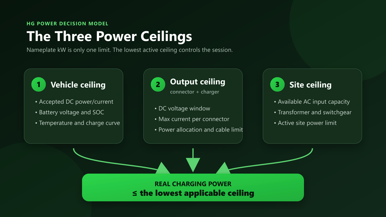
The most common sizing error is to compare chargers only by the largest kW number in a brochure. A 360 kW or 480 kW cabinet is capable of more total output than a 120 kW cabinet, but that does not mean every connected vehicle will receive the full rating.
Real charging power is no higher than the lowest applicable ceiling:
- Vehicle ceiling: what the EV requests and can accept at its present state of charge, battery temperature, voltage, and charging-curve position.
- Connector and charger-output ceiling: what the selected output can provide within its DC voltage range, maximum current, cable/thermal limit, and active power-allocation rule.
- Site ceiling: what the electrical service, transformer, switchgear, site controller, or configured power limit makes available to the charging system.
The US EPA makes the first ceiling explicit: the maximum power shown on a charger does not mean every EV can accept that much. EPA also notes that charging typically slows as the battery approaches full and can be affected by temperature and battery preparation. EPA: Watt’s Important? Seven Tips Every EV Driver Should Know
Why voltage and current must be read together
Power is the product of voltage and current:
Power (kW) = Voltage (V) × Current (A) ÷ 1,000
Suppose a connector has a 250 A maximum:
- At 400 V, the arithmetic ceiling is 100 kW.
- At 800 V, the arithmetic ceiling is 200 kW.
These are not charging-time promises. They simply show why a buyer cannot evaluate a charger by cabinet kW alone. The vehicle must request a compatible voltage, the connector must be allowed to supply the required current, the cabinet must have power available for that output, and the site must support the load.
The same logic applies to a multi-output cabinet. If one vehicle requests 100 kW and another requests 180 kW, the result depends on the cabinet’s combined limit, each connector’s limit, and the allocation strategy. A picture of two cables proves none of those values.
The Level-3-to-RFQ Translation
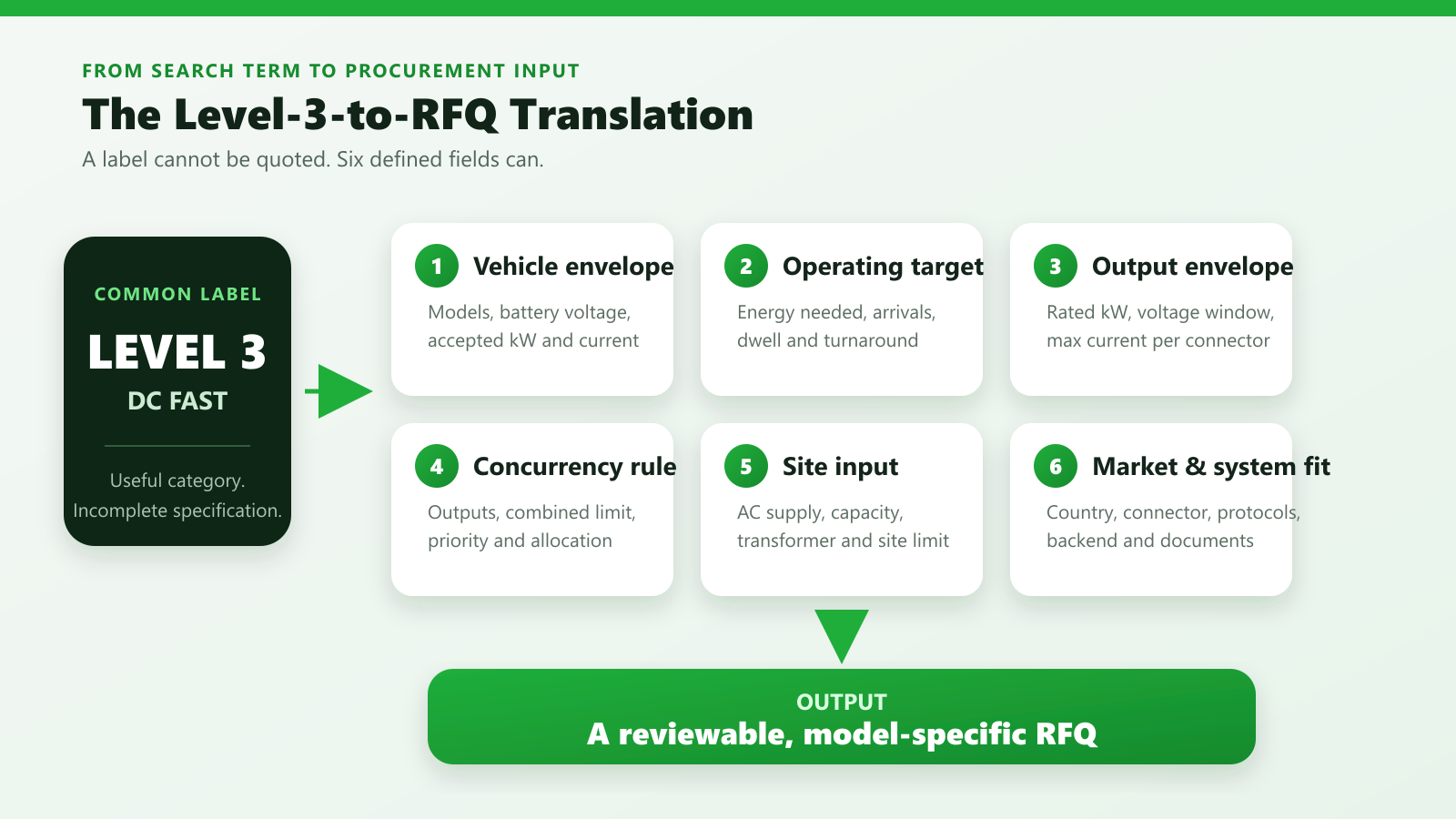
A useful RFQ replaces one vague label with six fields. Each field controls a different project decision and a different supplier deliverable.
| Required input | Decision it controls | What can fail if it is omitted | Deliverable to request |
|---|---|---|---|
| Vehicle models, battery-voltage range, accepted DC kW/current | Output envelope | Slow charging, current limitation, or incompatibility | Vehicle-to-charger compatibility review |
| Arrivals, energy needed, dwell/turnaround window | Power, port count, and operating plan | Under-sized throughput or over-sized hardware | Sizing assumptions and energy-per-window calculation |
| Rated kW, DC voltage range, max current per connector | Usable charger output | Nameplate rating cannot be used by the target vehicle | Model-specific datasheet |
| Number of outputs and allocation rule | Simultaneous service | Unexpected power splitting and queues | Written allocation logic and acceptance-test criteria |
| AC voltage, frequency, available capacity, site limit | Input configuration | Utility, transformer, or switchgear redesign | Installation manual and input/load data |
| Country, connector, EV protocol, OCPP/CSMS, required documents | Market and system fit | Failed vehicle session, backend integration, or acceptance | Exact option list, reports, certificates, and integration record |
This order is deliberate. Start with the transport operation, not the charger catalog. A technically impressive cabinet that does not fit the vehicles, operating window, site, or destination is still the wrong product.
Field 1: Define the Vehicle Envelope
A site does not charge a generic “EV.” It charges a known or planned fleet of vehicles, each with its own inlet, battery-voltage range, maximum DC power, current limit, and charging curve.
Collect these inputs for every important vehicle group:
- manufacturer and exact model;
- vehicle inlet/connector type;
- battery capacity, if available;
- usable DC voltage range;
- maximum accepted DC power and current;
- representative arrival state of charge;
- any cold- or hot-weather operating condition that matters;
- expected replacement vehicles during the project horizon.
Do not stop at peak kW. Peak acceptance may occur only within part of the charging curve. The EPA’s consumer guidance notes that DC fast-charging rate is generally higher when the battery is closer to empty and slows as it approaches full. EPA: Plug-in Electric Vehicle Charging – The Basics
For a mixed public site, the vehicle envelope should cover the range of vehicles the operator intends to serve. For a depot, it can be more exact because the fleet is known. For a distributor or EPC, the RFQ should identify the intended countries and vehicle segments rather than asking for an undefined “universal” charger.
Reality check: a 480 kW cabinet does not make every vehicle a 480 kW vehicle
If a vehicle requests less power, reaches its current limit, or begins tapering, extra cabinet capacity may remain unused for that session. Higher total cabinet power can still be valuable for future vehicles, multiple outputs, or a high-throughput operation, but those are separate justifications. They must be demonstrated by the operating plan.
Field 2: Convert the Operating Target Into Energy and Time
The next question is not “How fast is Level 3?” It is:
How much energy must reach how many vehicles within what operating window?
For each vehicle group, define:
- average and worst-case energy deficit on arrival;
- target departure state of charge or required route energy;
- dwell or turnaround time;
- daily number of charging events;
- peak arrivals per hour;
- simultaneous charging requirement;
- queue tolerance and operational priority.
A fleet that returns for eight hours has a different problem from a delivery vehicle that must leave again in 35 minutes. A retail site with irregular arrivals has a different problem from a depot with a controlled schedule. The correct design may involve more connectors at moderate power, fewer high-power outputs, scheduled charging, or a mixed architecture.
The energy-and-time target also creates an honest acceptance criterion. Instead of accepting “ultra-fast,” the buyer can ask whether the proposed system can deliver the required energy to the defined vehicles during the defined window, under stated power-sharing assumptions.
When not to overbuy DC fast charging
Do not select a high-power DC configuration merely because it is available when:
- vehicles remain parked long enough for lower-power charging to complete the job;
- the target vehicles cannot accept the proposed output;
- demand is too low to justify the site work;
- the available grid capacity cannot support the required operation;
- the project has not defined who will operate, monitor, and maintain the system.
“Level 3” is not automatically the best answer for every commercial parking space. It fits applications where the energy and turnaround requirement genuinely needs DC fast charging.
Field 3: Specify the Output Envelope, Not Just Rated kW
Once the vehicle and operating targets are known, compare equipment using at least these output fields:
- total rated output power;
- DC output-voltage range;
- maximum current per connector;
- number of outputs;
- maximum combined output;
- cable and connector thermal configuration;
- environmental derating conditions;
- efficiency at a stated operating point, when documented;
- supported vehicle-side communication, with version/feature scope.
A model-scoped HG Power example
The supplied Genesis CCS2 specification sheets illustrate why the fields must be read together. These are sheet-specific examples, not a statement that every HG Power product shares the same configuration.
| Supplied specification sheet | Rated total output | DC output window | Maximum current per connector | Number of outputs |
|---|---|---|---|---|
| Genesis CCS2 60 kW | 60 kW | 200–1000 VDC | 200 A | 2 |
| Genesis CCS2 120 kW | 120 kW | 200–1000 VDC | 250 A | 2 |
| Genesis CCS2 180 kW | 180 kW | 200–1000 VDC | 250 A | 2 |
| Genesis CCS2 360 kW | 360 kW | 200–1000 VDC | 350 A | 2 |
The 120 kW and 180 kW sheets, for example, list the same 250 A maximum per connector. At a lower vehicle voltage, that current line may limit the power available to one vehicle even though the 180 kW cabinet has more total capacity. The 360 kW sheet raises the listed per-connector maximum to 350 A, but the vehicle and active allocation still control actual use.
This is the procurement meaning behind the Three Power Ceilings: compare the complete output envelope with the vehicle envelope. Do not treat one number as the whole specification.
Field 4: Define What Happens When Two Vehicles Plug In
“Dual connector” can describe several different behaviors:
- two connectors are present, but only one operates at a time;
- both operate and split power equally;
- both operate with dynamic allocation based on vehicle requests;
- one connector has priority;
- both are individually capped;
- the site controller limits the cabinet or the full station.
The current HG Power source set used for this article does not establish one universal allocation algorithm across the portfolio. Therefore, the correct buyer action is to request the exact behavior for the quoted configuration.
Ask the supplier:
- Can both outputs charge simultaneously?
- What is the maximum combined output?
- What is the maximum output of each connector?
- Is allocation equal, dynamic, priority-based, or configurable?
- What happens when the two vehicles use different battery voltages?
- Can the charger or site controller enforce a site demand limit?
- Which logs or factory/site acceptance test will demonstrate the behavior?
A useful quotation should answer these questions in writing. “Two guns” is not an allocation specification.
Field 5: Verify the Site Input Before Freezing the Charger Model
High-power equipment is selected as part of an electrical system, not as a standalone appliance. DOE’s infrastructure guidance places planning, utility coordination, site design, equipment procurement, and installation in one connected process. DOE AFDC: Procurement and Installation for EV Charging Infrastructure
At minimum, establish:
- destination country and local grid arrangement;
- available AC voltage and frequency;
- three-phase capacity at the proposed connection point;
- transformer and switchgear capacity;
- existing peak load and planned site expansion;
- cable route, trenching distance, parking layout, and impact protection;
- any site-wide power-management ceiling;
- local utility, engineer, authority, and permitting requirements.
Do not copy a US 480 V design into a 380/400 V project – or copy a 380 V product sheet into a 480 V project – without confirming the actual input option. The supplied HG Power documents show this distinction: the reviewed CCS1 120–480 kW family manual lists 480 VAC ±15%, while the reviewed Genesis CCS2 60/120/180/360 kW sheets list 380 VAC ±15%. Those values belong to those named documents, not to the entire 40–480 kW portfolio.
The input calculation must also use the installation data for the quoted equipment. DC output kW is not a substitute for AC input current, efficiency, protection, or conductor design. Final design belongs with the local qualified professionals and authorities responsible for the destination site.
Field 6: Separate Connector, Vehicle Communication, Backend, and Documents
Four different questions are often compressed into “Is this charger compatible?”:
- Does the physical connector match the vehicle inlet?
- Can the vehicle and charger complete the required charging communication?
- Can the charger exchange the required data and commands with the selected management system?
- Does the exact product/document package meet the destination project’s requirements?
Passing one layer does not prove the next.
| Compatibility layer | Examples | What the buyer should verify |
|---|---|---|
| Physical and market interface | CCS1, CCS2, CHAdeMO, or SAE J3400 where available | Vehicle inlet, target-market plan, cable/current rating, and exact quoted connector |
| EV-to-EVSE communication | DIN 70121 or ISO 15118 where listed | Supported version/features and evidence with the target vehicle or simulator |
| EVSE-to-CSMS communication | OCPP version and target charging-management system | Required functions, security, certification status, and backend integration test |
| Destination evidence | Model-specific reports, certificates, declarations, manuals, and drawings | Exact legal entity, model/variant, standard edition, option, date, and local acceptance path |
Connector selection follows the vehicles and destination
DOE’s current US DC fast-charging discussion identifies CCS, CHAdeMO, and J3400 connector types. SAE’s formal J3400 record covers a coupler capable of AC or DC power transfer. Neither source means that one connector is universally correct or that every charger is available with every cable. DOE charging equipment guidance and SAE J3400 standard record
For a detailed treatment of CCS1, CCS2, vehicle-side communication, and procurement evidence, use the CCS charger buyer’s guide. The RFQ for this project should still name the actual vehicles and destination rather than requesting “CCS” alone.
OCPP does not prove vehicle compatibility
The Open Charge Alliance defines OCPP as the protocol between charging stations and charging-management systems. OCA also states that OCPP 1.6 and OCPP 2.0.1 are not backward compatible. A line that says “OCPP supported” is therefore incomplete without the version, required functions, security configuration, certification status, and target CSMS validation. Open Charge Alliance: OCPP and OCA FAQ
OCPP does not describe the physical vehicle connector, and it does not by itself prove a charging session with a particular EV. Keep the vehicle link and backend link as separate acceptance tests.
Certification language must stay model-specific
IEC’s official publication record identifies IEC 61851-23:2023 as a standard for DC EV supply equipment. That tells a buyer where part of the technical standards landscape sits; it does not certify a product. IEC 61851-23:2023
Ask for the certificate, associated report, declaration, installation manual, and nameplate information that match the exact quoted model and options. Then confirm the destination’s requirements with the responsible local professionals and authorities. A logo in a brochure is not a conformity package.
Match the Requirement to the Operating Situation
No responsible global guide can assign one kW rating to every hotel, highway, depot, or truck site. The useful output is a routing rule: identify which requirement dominates, then test the proposed configuration against it.
| Situation | Dominant input | Design emphasis | When not to overbuy |
|---|---|---|---|
| Commercial destination with long dwell | Parking duration and bay count | Enough accessible ports and managed site load | When lower-power charging can deliver the required energy before departure |
| Highway or public quick-turn site | Short session and mixed vehicles | Vehicle coverage, output envelope, payment/network operation, and serviceability | When the electrical/site path cannot support the intended throughput |
| Fleet or depot | Route energy, return window, dispatch peak | Schedule-based energy delivery and controlled concurrency | When overnight dwell can complete the job at lower power |
| Heavy-duty operation | Large energy deficit, current, cable handling, turnaround | High-current configuration, site capacity, layout, and thermal options | When the vehicles cannot use the proposed current or power |
| Capacity-constrained site | Site power ceiling | Managed power, staged deployment, or redesign of the operating target | When the upgrade is not justified by verified demand |
For the broader sequence from site demand through procurement, see the commercial EV charger buyer’s guide. Keep cost research in the dedicated commercial DC fast charger cost guide so this page can stay focused on specification quality.
Six Project Killers – and the Evidence That Exposes Them
The following problems often look like charger faults only after hardware arrives. In reality, most should be challenged during specification and acceptance planning.
| Symptom | Likely root cause | Verify before purchase | Required mitigation or deliverable |
|---|---|---|---|
| A vehicle never approaches the cabinet rating | Vehicle, SOC, temperature, voltage, or current ceiling | Vehicle data and representative charging curve | Match the complete output envelope and define a realistic energy/time target |
| Two vehicles charge much slower together | Allocation behavior was undefined | Combined output, per-connector limit, and dual-session test | Written allocation rule and acceptance criteria |
| The model changes after utility review | Site input was not confirmed first | Utility/load information and charger input manual | Freeze the electrical path before freezing the model |
| The plug fits but a session or integration fails | Physical, EV-protocol, or backend layer mismatch | Vehicle log, protocol scope, and CSMS test | Separate compatibility matrices and tests |
| A submitted certificate is rejected or irrelevant | Document does not match the model, option, market, or current requirement | Model nameplate, certificate, report, declaration, and destination checklist | Deliver one traceable model-specific document package |
| Higher kW adds no operational value | Vehicle or dwell target is the lower ceiling | Fleet energy and turnaround calculation | Select for measured throughput need, not headline power |
This table is also a supplier-screening tool. A credible proposal should make the assumptions visible and identify how each important behavior will be verified.
What HG Power Can Document – Within Exact Scope
HG Power’s approved commercial DC portfolio statement is 40–480 kW. That range describes the portfolio, not one universal cabinet or certificate.
Example 1: supplied CCS1 120–480 kW manual family
The technical-data pages in the supplied Genesis/Origin second-generation CCS1 manual list the named ANSI-DCL120B, ANSI-DCL180B, ANSI-DCL240B, ANSI-DCL360B, and ANSI-DCL480B models. The table lists:
- 120, 180, 240, 360, and 480 kW ratings;
- 480 VAC ±15%, 50/60 Hz input for that family;
- a 200–1000 VDC output range;
- 250 A maximum current, with 350 A shown as optional;
- dual CCS1 connectors and 5 m cables;
- DIN SPEC 70121 and ISO 15118 on the vehicle side;
- OCPP 1.6J on the backend side;
- Ethernet, 4G, and Wi-Fi interfaces;
- IP54 and forced-air cooling.
These are manual-listed family fields. A current quotation and matching model/option documents must confirm what is actually being supplied. None of these fields should be extended to 40–80 kW products, CCS2 products, or another cabinet family without its own evidence.
Example 2: supplied CCS2 60/120/180/360 kW sheets
The four inspected Genesis CCS2 sheets list dual CCS2 outputs, 200–1000 VDC, model-specific current lines, OCPP 1.6J with 2.0.1 shown as optional, and DIN 70121/ISO 15118. They also list 380 VAC ±15% input for those sheets.
Again, a specification-sheet protocol row does not prove every feature, protocol certification, or successful connection to the buyer’s backend. It tells the buyer what to verify in the quoted configuration and acceptance plan.
Example 3: lower- and upper-range conformity documents
A supplied wall-mounted DC charger conformity document names specific models including ENC-DCB040A and DCB040A. The document identifies LVD/EMC-related verification and lists standards in its annex, while explicitly stating that the voluntary verification cannot replace the EC Declaration of Conformity.
A separate 2025 supplied certificate identifies a named 480 kW split DC charging-station family, lists a 380 V AC input and DC 200–1000 V output line for the certificate scope, names applicable LVD/EN/IEC standards, and points to the associated full test report. The certificate also states that it is based on evaluation of one sample.
The procurement lesson is more important than the logos: match the legal entity, model, variant, electrical configuration, standard scope, certificate, associated report, and destination requirement.
Four layers of proof
Use this sequence whenever a supplier makes a broad claim:
- Portfolio: what the manufacturer offers across all product families.
- Manual family: which named models one manual or sheet actually covers.
- Quoted configuration: connector, input, output, software, cooling, options, and accessories in the commercial offer.
- Destination package: the exact reports, certificates, declarations, drawings, and installation requirements for the project.
Evidence at one layer does not automatically prove the next.
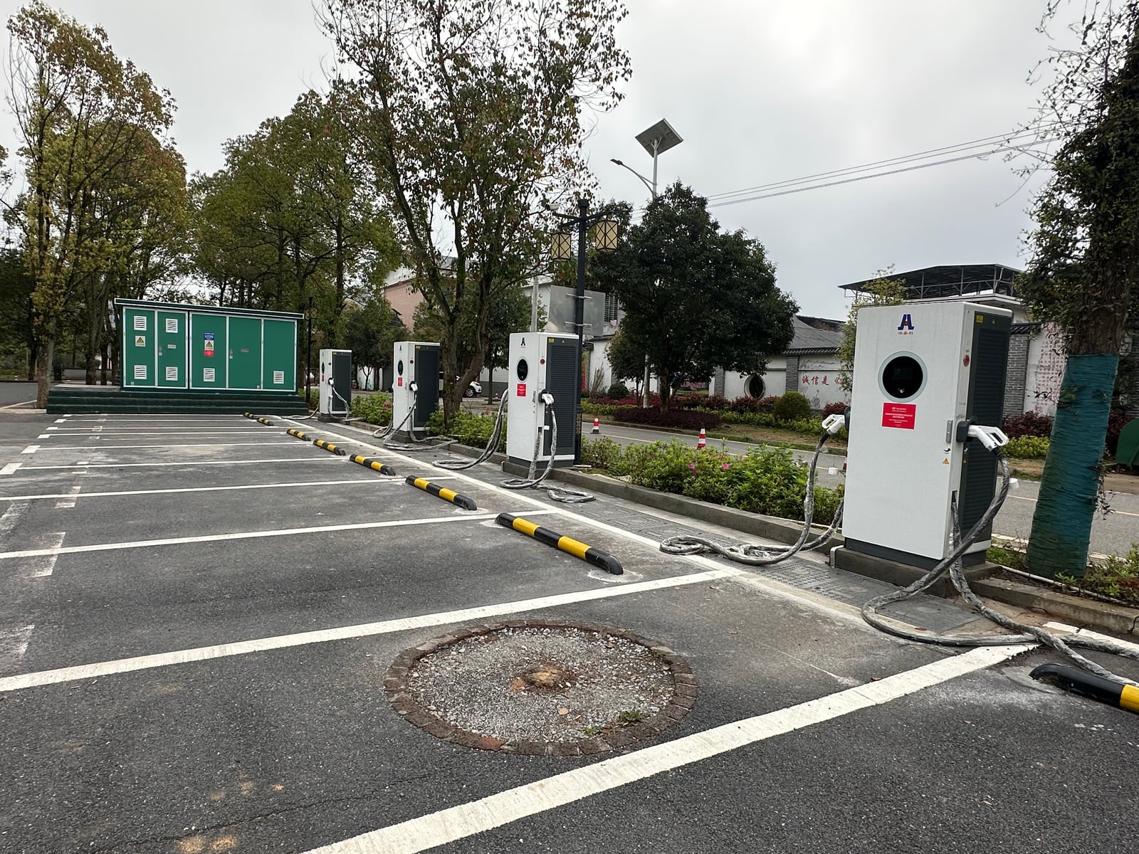
First-party project context: A supplied HG Power project record identifies a Chenzhou, Hunan installation with four 400 kW heavy-duty charging units. The photograph documents the physical station arrangement and upstream equipment. It does not establish measured output, uptime, throughput, or commercial results.
Buyers can review HG Power’s product specifications and manuals, certification resources, and project case studies as starting points. The final evidence package must still match the quotation.
Copyable Level 3 Charger RFQ Checklist
Send the following information to obtain a reviewable configuration instead of a generic price:
Vehicles and operation
- Destination country:
- Vehicle makes/models:
- Vehicle inlets/connectors:
- Battery-voltage range:
- Maximum accepted DC power/current:
- Typical and worst-case arrival SOC:
- Energy needed per vehicle:
- Required departure SOC or route energy:
- Dwell/turnaround window:
- Daily sessions and peak arrivals:
- Simultaneous charging requirement:
Site
- Available AC voltage and frequency:
- Three-phase capacity at the connection point:
- Transformer/switchgear details:
- Existing peak load or available headroom:
- Proposed cable route and charger locations:
- Site power-management limit:
- Environmental/altitude conditions:
Equipment, system, and evidence
- Preferred number of outputs:
- Required combined/per-connector behavior:
- Connector and cable requirements:
- Authentication and payment:
- Target CSMS and OCPP version/functions:
- Required vehicle-side protocol/features:
- Required reports, certificates, declarations, and drawings:
- Quantity and project schedule:
If the full site study is not ready, start with the destination country, vehicle list, energy/turnaround target, and a clear record of the electrical-service nameplate or available supply. Those four inputs are enough to expose many incompatible assumptions.
Frequently Asked Questions
Is a Level 3 electric car charger the same as a DC fast charger?
In common US usage, usually yes: DOE says DC fast charging is also referred to as Level 3. For a technical RFQ, write “DC fast charger” and then define power, voltage, current, connectors, allocation, input, communications, and documents.
How many kW is a Level 3 charger?
The label does not establish one universal kW rating. DOE’s current page discusses installed DC fast equipment up to 500 kW, but individual products and vehicles cover different ranges. Select power from the vehicle, energy, time, concurrency, and site requirements.
Can a Level 3 charger be installed at home?
It is generally a commercial/industrial infrastructure decision rather than a normal home-charging choice. Feasibility depends on the local electrical service, utility, equipment, site, approvals, and cost. For most homes, lower-power AC charging better matches overnight dwell. Do not treat this as a universal legal prohibition; ask the local utility and qualified professionals.
Does a 480 kW charger always charge faster than a 120 kW charger?
No. It offers a higher total cabinet ceiling, but the vehicle’s requested power, battery voltage, current limit, charging curve, connector limit, allocation, and site limit can all reduce delivered power. Higher capacity must be justified by the vehicle mix or simultaneous-throughput requirement.
What electrical supply does a commercial DC fast charger need?
Use the exact installation manual for the quoted input option and confirm it against the destination site. Do not assume one global voltage. The reviewed HG Power source set, for example, includes a CCS1 family manual listing 480 VAC and CCS2 sheets listing 380 VAC.
Can two EVs charge at the same time?
Only if the quoted configuration supports simultaneous operation. Ask for the maximum combined output, maximum per connector, allocation rule, behavior with different vehicle voltages, and a dual-session acceptance test. Two visible cables alone do not answer the question.
Which connector should an international project specify?
Start with the actual vehicle inlets and destination-market plan. Then verify the exact cable/current option, vehicle-side communication, and supporting documents. Do not assume that every power rating is available with CCS1, CCS2, CHAdeMO, or J3400.
What information is needed for a Level 3 charger quotation?
At minimum: destination country, vehicle list, energy and dwell target, expected concurrency, available AC supply, connector preference, backend/payment requirements, required documents, quantity, and schedule.
Technical Review and Sources
Technical reviewer: Marvin
Primary external references:
- U.S. DOE Alternative Fuels Data Center – Electric Vehicle Charging Stations
- U.S. DOE Alternative Fuels Data Center – Procurement and Installation
- U.S. EPA – Plug-in Electric Vehicle Charging: The Basics
- U.S. EPA – Watt’s Important?
- IEC 61851-23:2023 official publication record
- SAE J3400 official standard record
- Open Charge Alliance – OCPP
First-party scope reviewed for this guide:
- HG Power CCS1 120–480 kW second-generation manual, technical-data pages 101–103.
- HG Power Genesis CCS2 60/120/180/360 kW specification sheets.
- Specific supplied wall-mounted DC charger and 480 kW split-station conformity documents.
- Supplied first-party project photographs and project-folder records.
Get a Project-Specific Configuration Review
Send your destination country, vehicle list, expected arrivals, energy and dwell target, available AC supply, connector preference, backend/payment requirements, and required documents. HG Power can map those inputs to a 40–480 kW DC charging configuration for technical review.
Request a project-specific configuration
Final equipment, conformity, utility, and installation requirements remain model- and destination-specific.
Reviewed by Marvin
Product statements are limited to the supplied HG Power manuals, specification sheets, conformity documents, and first-party project records. Final electrical design, equipment selection, and destination-market acceptance require exact-model review by the responsible qualified parties.