
Off-Grid Solar EV Charging Station: PV, Battery, Autonomy and DC Site Design
Separate charger kW, daily kWh, autonomy and recovery—then prove the worst operating period before choosing equipment.
Direct answer: An off-grid solar EV charging station combines PV generation, battery storage, power conversion, charging equipment and an energy-management controller without depending on a continuous utility supply. Size it with four ledgers: the highest simultaneous charging power, daily delivered energy, usable battery energy through the declared low-sun interval, and recovery power after that interval. A credible proposal must also show vehicle limits, critical loads, SOC reserve, load-shedding logic, backup strategy and witnessed acceptance tests.
When does an off-grid solar EV charging station make sense?
The architecture fits locations where a utility connection is unavailable, unreliable, delayed or disproportionately expensive relative to the charging mission. Candidates include remote fleets, mines and construction sites, parks and resorts, rural service points, temporary infrastructure and selected corridor locations.
It may be the wrong solution when the daily EV duty is much larger than the available land and solar resource, when the operator requires unconstrained 24/7 fast charging but refuses firm backup, or when a modest grid extension provides the same service with less lifecycle complexity. “Off grid” removes utility dependence; it does not remove weather, maintenance, civil works, protection, communications or permitting.
HG Power’s existing solar-powered EV charging guide owns broad feasibility, cost and ROI. The solar-storage-charging overview explains the technology family. This guide answers the narrower engineering question: how much charging service can a no-grid site defend through its worst operating period, and what evidence should a buyer demand before ordering?
Define the complete system boundary
A commercial off-grid charging site is more than panels connected to a charger. Its boundary normally includes:
- PV array: modules, mounting, strings, combiners, disconnects and lightning/surge protection.
- PV conversion: MPPT and DC/DC or PV inverter equipment, with a declared voltage/current window.
- Battery energy storage system (BESS): cells, BMS, contactors, thermal management, fire/safety functions and an approved operating SOC window.
- Power conversion: PCS, inverter or shared DC-bus equipment that forms and regulates the local electrical system.
- EV charging equipment: connector, vehicle communication, output voltage/current envelope, power allocation and session metering.
- Energy management system (EMS): dispatch, forecasting, priorities, alarms, data logging and fault-safe states.
- Site loads: lighting, networking, payment, security, cooling, workshops or other loads that compete with EV charging.
- Optional firm backup: generator, weak grid or another dispatchable source when the service target cannot tolerate weather-only supply.
The U.S. Department of Energy describes resilient solar-plus-storage as a controlled microgrid problem: solar panels alone do not establish islanded operation. A properly configured inverter/controller and storage are required to maintain local power when the utility is absent. For procurement, the quotation must state which party owns every interface and who proves the combined system—not only the individual components.
Ask for a single-line diagram with energy meters and control links. If PV, BESS, PCS and charger come from different suppliers, require one named system integrator to own interface testing and the final settings backup.
Build the vehicle and site-load record first
Do not start with “we need a 120 kW charger.” Start with the transport duty.
For each vehicle group, record:
- connector and applicable communication standard;
- battery voltage and the expected voltage range during charging;
- maximum vehicle current and charging acceptance curve;
- arrival and departure times;
- arrival SOC and minimum departure SOC;
- energy required at the inlet;
- number of simultaneous sessions;
- which departures are critical and which can be delayed.
Add every non-EV load and classify it as critical, deferrable or shed-able. Then build an hourly or sub-hourly profile. Fifteen-minute data is useful for an early energy model; the final power/control study may need finer resolution for charger steps, cloud ramps and source transitions.
| Required input | What it controls | Failure when omitted |
|---|---|---|
| Energy by departure | minimum daily and per-window kWh | vehicles leave below target SOC |
| Arrival/departure distribution | overlap and scheduling flexibility | design assumes impossible solar-aligned charging |
| Vehicle voltage/current curve | real charging power | time estimate assumes constant nameplate kW |
| Concurrent connectors | peak DC and upstream demand | second session causes derating or trip |
| Critical site loads | reserved kW and kWh | charging drains safety/operations reserve |
| Seasonal operating calendar | worst duty and solar overlap | annual average hides the design period |
For a depot-specific scheduling method, use the fleet EV charging guide. For the wider site survey and commissioning sequence, see the DC fast charger station guide.
Decision model 1: Four-Ledger Sizing
One load record must pass four different checks
vehicle ceiling
→
departure
→
→
charger · EMS
protected reserve
→
before next duty
→
→
not nameplates
A larger battery cannot fix a persistent energy deficit, and a larger PV array cannot cover a night-time power step without a suitable buffer or firm source.
One equipment rating cannot answer four different questions.
Ledger 1 — Session power (kW)
Can the site deliver the highest required charging power while critical loads remain online?
At any instant:
available source and storage power ≥ charger input + critical loads + conversion losses + required control reserve
The real power into the vehicle is limited by the lowest active ceiling:
real charging power ≤ min(charger, vehicle acceptance, allocated output, PCS/DC bus, BESS/source power, thermal and ambient limits)
This is why a 120 kW charger does not guarantee a 120 kW session and why a 120 kWp PV array does not directly “run” a 120 kW charger.
Ledger 2 — Daily energy (kWh)
How much energy must the system deliver and replace over the operating day?
daily delivered energy = Σ EV inlet energy + critical-load energy
source-side daily energy = daily delivered energy / modeled path efficiency
The model should show each conversion path rather than applying one optimistic system-wide efficiency. Daytime PV-to-vehicle, PV-to-battery-to-vehicle and backup-to-battery-to-vehicle paths do not have identical losses.
Ledger 3 — Autonomy energy (kWh)
How much usable battery energy must remain available through the declared low-sun interval?
usable battery energy = nominal energy × approved SOC window × applicable discharge-path efficiency
Then simulate the actual time series:
autonomy deficit = load(t) - firm generation(t)
Do not convert nominal battery kWh directly into “number of vehicle charges.” Reserve SOC, temperature, ageing, PCS efficiency, auxiliaries and vehicle-path losses reduce what reaches the inlet. More importantly, the battery must preserve critical loads and the recovery plan—not only finish the current session.
Ledger 4 — Recovery power (kW)
After a cloudy period or high-duty shift, can the site rebuild reserve before the next critical departure?
average recovery power = energy needed to restore target SOC / available recovery time
Add concurrent EV and site loads. A battery may survive the first low-sun day and still fail operationally because the PV array or backup source cannot restore it before the next duty cycle.
The four ledgers must be evaluated together. Larger storage can increase autonomy, but it cannot repair a persistent daily energy deficit. More PV can increase recovery, but it cannot satisfy a night-time 120 kW power step without a suitable buffer or firm source.
Size PV from the worst relevant period, not the annual average
Start with hourly solar data for the actual coordinates, array orientation, shading, temperature and soiling assumptions. NREL’s PVWatts is useful for a preliminary production estimate and makes its location, module, array and loss assumptions explicit. It is an estimate, not a performance guarantee, and more detailed tools may be required for complex terrain or system architecture.
An early energy relation is:
PV energy for the period = installed PV kWp × modeled site yield (kWh/kWp for that period)
But the design decision requires a time series. Test at least:
- the lowest relevant seasonal production;
- the highest declared vehicle duty;
- cloud events during active charging;
- consecutive low-solar days;
- full-battery/low-demand periods that cause curtailment;
- maintenance or partial-array outages where relevant.
NREL’s resilience guidance recommends sensitivity tests around outage timing, critical load, low winter solar and system size. Apply the same discipline to a permanently off-grid site. “Average day” is useful for energy economics; it is not the acceptance case for availability.
Land can also become the limiting input. A buyer should provide usable area, slope, structural limits, shading, drainage, wind/snow/environmental criteria and permitted vegetation management. Array orientation may be chosen to match the charging window rather than maximize annual kWh alone.
Size the battery three ways
Battery procurement requires energy, power and recovery checks.
1. Usable energy
Use the ordered battery’s warranted SOC window, temperature limits, degradation model and discharge-path efficiency. Keep an explicit reserve for critical loads and fault recovery. A vendor’s maximum DoD value is not automatically the operating setpoint.
2. Deliverable power
The BESS and PCS must cover the maximum source-load gap, including charger ramp, cloud ramp and any start interval for backup generation. Confirm continuous power, short-duration power, current, DC-bus voltage, thermal derating and auxiliary consumption.
A system can contain sufficient kWh and still trip or throttle because its PCS, BMS, cabling or cooling cannot deliver the required kW.
3. Recharge/recovery capability
Confirm how quickly the system can absorb PV or backup energy after a deficit, while serving concurrent loads. Battery charge power, PV conversion power and thermal limits can make recovery slower than a simple kWh division suggests.
The quotation should state:
- nominal and usable energy at beginning of life;
- continuous and short-duration charge/discharge power;
- approved SOC window and protected reserve;
- temperature and altitude derating;
- warranted degradation/augmentation assumption for the modeled duty;
- simultaneous charge/discharge restrictions;
- communications-loss behavior;
- thermal-management and standby energy;
- replacement and service boundary.
A worked sizing structure—not a quotation
Consider a hypothetical remote site that must deliver 360 kWh to vehicles per day and 24 kWh to critical loads. Suppose the design team models an 88% combined source-to-load efficiency for the relevant paths. The source-side daily requirement would be:
(360 + 24) / 0.88 = 436 kWh/day
That result does not select the PV array. If the worst-month modeled yield is 3.2 kWh/kWp/day, an uncorrected energy balance would suggest about 136 kWp. Real design still has to add the project’s availability margin, curtailment, degradation and recovery target, then run hourly dispatch. A 136 kWp array also cannot guarantee a 120 kW session at night.
If a declared low-sun interval leaves a 300 kWh cumulative deficit, and the ordered battery is modeled with an 80% operating SOC window and 94% discharge-path efficiency, the early nominal-energy check is:
300 / 0.80 / 0.94 = 399 kWh nominal
The result still needs reserve, ageing, temperature and power checks. It is an example of method, not an HG Power configuration or a recommended universal margin.
Finally, if the system must restore 240 kWh of reserve within six hours while serving a 20 kW concurrent average load, the early recovery check is:
240 / 6 + 20 = 60 kW average at the receiving boundary
The source-side requirement will be higher after conversion and charging losses. Only a time-series model can show whether the PV/backup profile actually supplies that recovery window.
Decision model 2: The Worst-Period Energy Test
Define one reproducible design interval. It might be the lowest-solar week of the operating season, a monsoon/cloud sequence, a winter duty period, or another locally justified case. Do not silently choose the worst meteorological event on record; agree the reliability target, dataset and exceedance method with the buyer.
Run the same interval through at least four scenarios:
- Expected duty / expected solar — checks normal dispatch and curtailment.
- High duty / low solar — checks autonomy, load shedding and backup use.
- Critical departure after deficit — checks reserved energy and priority logic.
- Component unavailable — checks degraded operation with one declared element out of service.
Report at every time step:
- EV and site-load demand;
- PV production and curtailment;
- BESS SOC, charge/discharge kW and operating limit;
- charger allocation and unmet/deferred energy;
- backup energy/runtime where applicable;
- critical-load service;
- alarms and state transitions.
The acceptance criterion should be stated as a service result, such as “all priority vehicles receive their required inlet energy by departure while critical loads remain supplied and SOC never crosses the protected floor.” It should not be “the model contains a 261 kWh battery.”
Decision model 3: Write Five Operating States before ordering
Five states make the controller promise testable
Each state needs a trigger, power limit, SOC rule, fallback action and recorded acceptance case.
| State | Typical trigger | Energy path | Required controller action | Proof |
|---|---|---|---|---|
| 1. Solar surplus | PV exceeds active loads and BESS can accept energy | PV → loads, then BESS | charge within limits; curtail when storage/loads cannot absorb | trend of PV, load, SOC and curtailment |
| 2. Normal solar + storage | PV is available but below or above instantaneous charging demand | PV + BESS → charger/site | follow session priority and maintain reserve | stable multi-session operation with critical loads |
| 3. Cloud or charge step | PV falls or charger demand rises rapidly | BESS bridges the difference | hold bus conditions; enforce PCS/BMS and allocation limits | witnessed cloud/load-step test |
| 4. Reserve protection | SOC/forecast reaches approved threshold | PV/backup → critical loads and allowed charging | derate or defer non-critical sessions; alarm; start backup if designed | protected-floor and load-shedding test |
| 5. Recovery or fault | solar returns, backup starts, or a component/communication fault occurs | controlled recharge or safe degraded state | restore reserve without violating charge power; record events; apply fault matrix | recovery-time test, fault injection and event log |
Add separate states when the project includes a weak grid, generator, second BESS string or vehicle-to-site function. The controller narrative must state start/stop thresholds, hysteresis, forecast use, manual override, communication timeout and what happens when the forecast is wrong.
For a generator-backed variant, use the separate diesel-PV-battery hybrid guide, which adds generator loading, fuel and maintenance tests.
Choose the electrical boundary deliberately
| Architecture | Possible advantage | Buyer must verify | Common hidden issue |
|---|---|---|---|
| AC-coupled PV/BESS feeding a conventional DC charger | familiar equipment boundaries and AC site-load integration | inverter/PCS power, grid-forming behavior, harmonics, transfer, protection and conversion losses | one or more conversion stages omitted from energy model |
| DC-coupled PV/BESS/charger | may reduce conversion stages and use a shared DC bus | voltage windows, isolation, DC fault protection, switchgear, controls and destination acceptance | incompatible voltage ranges or unclear fault ownership |
| Hybrid AC/DC | lets specific sources and loads use a suitable bus | exact ordered energy paths and operating states | proposal lists every option but no single testable topology |
No architecture wins by label. Compare the exact energy paths, serviceability, standards, spares and test responsibility. Require an as-built single-line diagram and settings register.
What the supplied HG Power manual documents
HG Power’s public DC charger portfolio spans 40–480 kW, but that portfolio range does not define an off-grid solar system. The supplied GCC261K-125 Integrated Solar Storage Charging System manual documents one configuration boundary:
| Manual item | Documented value | Buyer interpretation |
|---|---|---|
| Nominal storage | 261 kWh | not the same as usable EV-delivered energy |
| Battery charge/discharge power | 125 kW | confirm continuous/ambient/thermal limits in the order |
| Battery voltage | 728–949 Vdc | coordinate with PCS/DC-bus equipment |
| DC charging module | nominal 120 kW, two guns | confirm allocation; not 120 kW per gun by default |
| Charger output envelope | 200–1000 Vdc, max 200 A | real vehicle power still follows voltage/current acceptance |
| PCS | 125 kW, grid-connected/off-grid modes | black start, transfer and project control sequence require test evidence |
| Cell chemistry | 314 Ah LFP cells | does not by itself establish system certification or project life |
The manual lists model-specific/default SOC settings and a maximum DoD value, but those are not universal sizing rules. The approved operating reserve must come from the ordered warranty, duty cycle and resilience target. Its charger section references a GB/T configuration; connector and conformity requirements for another destination must be specified and verified separately.
The same manual contains inconsistent illustrative PV string counts, so exact array stringing is intentionally excluded here. The final design must be based on the selected module datasheet, temperature-corrected Voc, MPPT windows, current limits and destination electrical requirements.
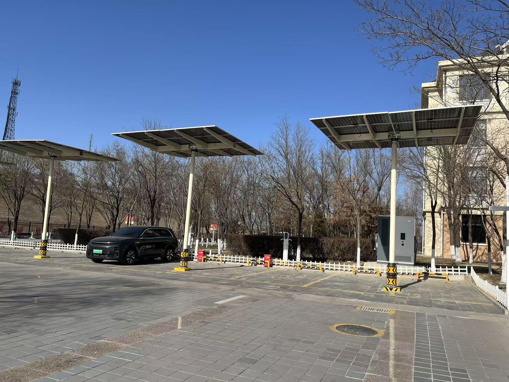
The supplied project photograph shows PV canopies and installed charging equipment. It establishes visual project context only. It does not prove that the site is fully off grid, its ratings, energy yield, autonomy, uptime or commercial return.
Six project killers and how to expose them
| Symptom | Likely root cause | Verification | Mitigation |
|---|---|---|---|
| SOC declines every day | persistent energy deficit | multi-day PV/load/SOC balance | add firm energy/PV, reduce or reschedule duty |
| Charger throttles despite a large battery | PCS/BMS/DC-bus power limit | high-resolution power and limit trace | resize power path or manage allocation/ramp |
| Priority vehicle misses departure target | schedule and reserve not modeled | replay arrival/departure and SOC record | reserve energy and encode session priority |
| Full battery at noon but low SOC before morning duty | curtailment and load timing mismatch | PV, curtailment, SOC and session trend | shift charging, expand useful load or revise storage/PV balance |
| Site goes dark after one communications fault | undefined fallback state | fault matrix and witnessed disconnect test | local fallback control and protected critical bus |
| Supplier claims autonomy but cannot show assumptions | nominal kWh used as proof | request time-series input/output file | define weather, duty, SOC, losses and acceptance criterion |
Decision model 4: The Off-Grid Acceptance Ladder
1. Design review
Approve the single-line diagram, equipment schedule, vehicle/load dataset, solar dataset, four ledgers, state table, protection philosophy, communications map, meter boundaries, assumptions register and destination compliance matrix.
2. Time-series simulation
Run the agreed normal, low-sun, high-duty, critical-departure and degraded-component cases. Export PV, loads, charger allocation, SOC, curtailed/deferred energy, reserve violations and backup use.
3. Factory acceptance test (FAT)
Witness charger load steps, PV/source emulation, SOC thresholds, output allocation, derating, reserve protection, alarms, emergency stop, communications loss and recovery. A screen menu is not evidence that a function works.
4. Site acceptance test (SAT)
Repeat the agreed cases with installed switchgear, grounding, protection, meters, communications, charger cables and site loads. Verify array polarity/insulation, BESS/PCS limits, emergency functions, meter reconciliation and remote/local control.
5. Operating-data review
After an agreed period, compare real vehicle duty, PV, curtailment, SOC, charger energy, critical-load service and alarms with the design model. Tune thresholds only under change control and retain the approved settings backup.
Twelve inputs for a comparable off-grid RFQ
| # | Input the buyer provides | Supplier response required |
|---|---|---|
| 1 | destination and site coordinates | applicable conformity/installation boundary and solar dataset source |
| 2 | vehicle models, inlets and voltage/current limits | compatibility matrix and test plan |
| 3 | arrival/departure schedule and energy per vehicle | time-series charging allocation |
| 4 | maximum concurrent sessions | charger/port allocation and peak source-load gap |
| 5 | critical and deferrable site loads | priority and load-shedding table |
| 6 | required service level and declared low-sun interval | autonomy criterion and unmet-load result |
| 7 | usable PV area, shading and structural/environmental constraints | array layout, modeled yield and assumptions |
| 8 | battery reserve, lifecycle and warranty target | nominal/usable kWh, kW, SOC window and degradation model |
| 9 | permitted backup source and runtime, if any | backup rating, trigger, recovery and fuel/grid assumptions |
| 10 | ambient temperature, altitude, dust, humidity, salt/snow/wind conditions | equipment and output derating plus enclosure/thermal option |
| 11 | communications, payment, backend and reporting needs | interfaces, offline behavior, logs and cybersecurity boundary |
| 12 | FAT/SAT cases, documentation and spares | witnessed test matrix, deliverables, warranty and service scope |
Ask every bidder to return the same four-ledger summary and time-series scenario. Otherwise one quotation may optimize a sunny average day while another prices the declared worst period, making the totals incomparable.
Frequently asked questions
Can an EV charging station run completely off grid?
Yes, if PV, storage, power conversion, controls and any backup source are sized for a defined vehicle and site-load duty. “Completely off grid” does not mean unlimited charging: service remains constrained by instantaneous power, accumulated energy, weather, reserve policy and recovery time.
Can solar panels directly run a DC fast charger?
They can contribute directly through a compatible DC-coupled architecture, but variable irradiance and vehicle demand still require voltage regulation, protection and coordinated control. Many commercial designs use a battery and PCS/DC bus to buffer fast changes and support charging outside strong-sun periods.
How much solar is needed for an off-grid EV charging station?
Calculate the site’s source-side kWh over the design period, then model PV production for the actual coordinates, array and losses. Use the worst relevant season and run hourly/sub-hourly dispatch. Dividing charger kW by panel wattage does not size the system.
How large should the battery be?
Size usable kWh for the declared low-sun deficit and reserve, continuous/short-duration kW for the largest source-load gap, and charge power for the required recovery window. Nominal capacity alone cannot prove autonomy or fast-charge performance.
Is a backup generator required?
Not always. It depends on solar resource, land, duty flexibility, service target and the acceptable probability/duration of deferred charging. A firm backup may be economically or operationally justified when critical departures must continue through extended low-sun periods.
Does off-grid charging eliminate civil work and permits?
No. Some packaged systems can reduce trenching or utility-interconnection work, but foundations, structural work, drainage, grounding, access, fire/safety provisions, environmental review and local approvals may still apply.
What should be tested before handover?
Test the agreed operating states: charger load steps, source changes, SOC thresholds, priority/load shedding, low-sun recovery, communications loss, alarms, emergency stop and meter reconciliation. Tie every test to an acceptance criterion and retained log.
Turn an off-grid concept into a testable configuration
Send HG Power the site coordinates, vehicle schedule, energy by departure, maximum concurrency, critical loads, available PV area, autonomy target, backup policy, environmental conditions, destination requirements and FAT/SAT cases. The engineering response should return a configuration-bound energy-flow diagram, four-ledger summary, operating-state table and assumptions list—not only charger and battery nameplates.
Technical review: Marvin, HG Power
Planning note: Final electrical, structural, fire, environmental, accessibility, metering, payment and conformity requirements must be verified for the destination and the ordered configuration.
Sources
- U.S. Department of Energy, Microgrid System Project Development Checklist, 2025.
- U.S. Department of Energy, Solar and Resilience Basics.
- U.S. Department of Energy Grid Deployment Office, Microgrid Overview.
- NREL, PVWatts Calculator.
- NREL, REopt and REopt Lite Overview—Resilience.
- Alternative Fuels Data Center, Public EV Charging Station Site Selection Checklist.
- Alternative Fuels Data Center / USDOT, Charging Forward: A Toolkit for Planning and Funding Rural Electric Mobility Infrastructure.
- NREL, Technology Tips for Solar + Storage (NREL/TP-7A40-90582).
- HG Power,
GCC261K-125 Integrated Solar Storage Charging System User Manual V2.0_20251112, supplied first-party manual. - HG Power,
2026 Hongjiali New Energy Optical-Storage-Charging-Swapping Solution, supplied first-party presentation.