
350 kW DC EV Charger: Vehicle Fit, Site Requirements and RFQ Guide
A configuration-first guide to vehicle acceptance, site import, connector limits, power sharing and FAT/SAT evidence.
Direct answer: A 350 kW DC charger is a high-power equipment rating, not a promise that every vehicle or connector will receive 350 kW. Before procurement, verify the vehicle’s voltage/current request, usable energy window, connector and cable boundary, concurrent-session allocation, site import and the exact FAT/SAT evidence. If any ceiling is unknown, keep the rating provisional and request a configuration-specific quotation.
What does a 350 kW DC EV charger actually mean?
The label normally describes a rated DC output envelope for a charger, cabinet or system. The label alone does not tell a buyer whether the number applies to one connector, several dispensers, a shared cabinet, a short peak, a sustained operating condition, or a particular input and temperature range.
It also does not tell you what the connected vehicle will request. At a given moment, DC power is constrained by the vehicle battery system, state of charge, temperature, connector and cable, charger output limits, concurrent sessions and the site operating cap. The charger can be rated higher than the vehicle’s present request and still deliver less power.
The U.S. Department of Energy describes charging time as dependent on state of charge, battery capacity, vehicle factors, equipment output and electrical-service specifications.[1] That is why a responsible 350 kW quote must define the complete operating boundary, not just print “350 kW” in a product title.
The 350 kW Label Translation Ladder
Translate the headline rating into a testable record
Each arrow is a verification point; no arrow is a performance promise.
Use this ladder to turn a headline rating into a procurement record:
350 kW label → voltage/current envelope → cabinet and dispenser topology → connector/cable ceiling → vehicle request → site operating cap → witnessed acceptance record
If one arrow is missing, the number is not yet comparable with another supplier’s number.
1. Rated power
Ask whether 350 kW is a cabinet total, an output per dispenser, an aggregate limit, or a maximum under stated conditions. Ask for the input basis and whether the figure is continuous, peak, or otherwise conditioned.
2. Voltage and current
Power follows the basic relationship:
P (kW) = V (V) × I (A) ÷ 1,000
At 700 V and 500 A, the arithmetic ceiling is 350 kW. That equation is useful for checking a quotation, but it does not prove that a charger can operate across that full combination, that the cable supports it, or that a vehicle will request it. The voltage and current range must be tied to the exact ordered model and connector.
3. Topology
A 350 kW system can be presented as an integrated cabinet, a power cabinet feeding dispensers, or another architecture. The topology affects cable routes, maintenance isolation, expansion, power sharing and how the buyer should read the output table.
4. Vehicle request
The vehicle’s battery-management system controls its charging request within the limits of the vehicle, battery, temperature and session state. A vehicle with a lower acceptance ceiling will not become a 350 kW vehicle because the station nameplate is higher.
5. Site cap and evidence
The utility connection, transformer, switchgear, protection, other coincident loads and energy-management policy can restrict the station’s operating envelope. The final record is the configuration, FAT and SAT evidence for the ordered build.
Start with the vehicle duty, not the charger number
Before comparing 350 kW products, write a duty ledger for representative vehicles:
| Input | Why it changes the decision | Evidence to request |
|---|---|---|
| Arrival state of charge | Determines energy still required. | Route or dispatch assumption. |
| Departure target | Defines the required energy before the vehicle leaves. | Duty-cycle record. |
| Usable charging window | A parked vehicle may not be connected for the entire dwell. | Access, queue, loading and dispatch assumptions. |
| Vehicle voltage/current request | Sets the active electrical ceiling. | OEM data or a witnessed vehicle test. |
| Battery temperature and charge curve | Peak power may not persist through the session. | Vehicle acceptance information and test conditions. |
| Session overlap | Determines whether power is shared between vehicles. | Arrival/departure distribution or dispatch schedule. |
The planning baseline is:
Average power baseline (kW) = required energy (kWh) ÷ usable charging window (h)
For an illustrative 140 kWh requirement and a two-hour usable window, the baseline is 70 kW. That does not mean a 70 kW charger is automatically sufficient, and it does not mean a 350 kW charger is automatically necessary. The vehicle curve, overlap, site cap and operating policy still decide the usable result.
Can every EV use a 350 kW charger?
No. Compatibility must be checked across the vehicle inlet, connector standard, voltage and current request, cable boundary and charge-control behavior. The Welsh Government procurement note says maximum speed is dictated by the vehicle and stresses compatibility between charge points and the vehicles that will use them.[2]
The buyer should request a vehicle acceptance matrix rather than a sentence saying “compatible with all EVs.” The matrix should identify:
| Field | Required answer |
|---|---|
| Vehicle and model year | Which representative vehicles are in scope? |
| Inlet and connector | CCS1, CCS2, NACS/J3400, CHAdeMO or another approved interface? |
| Vehicle voltage range | What voltage range does the vehicle request during the planned session? |
| Maximum vehicle current | What is the vehicle-side current ceiling? |
| Charge curve | What happens from arrival state of charge to departure target? |
| Test condition | Which cable, ambient condition, starting state and meter are used? |
| Acceptance result | What values were requested, delivered and recorded? |
The matrix is also where a buyer can identify a mixed fleet. A station may serve multiple vehicle classes, but the exact result depends on each vehicle’s request and the station’s allocation behavior.
Is 350 kW per connector or per charger?
It may be either, and the quotation must say which. Do not infer per-connector output from a cabinet headline.
| Quotation wording | Question to ask | Failure if it remains undefined |
|---|---|---|
| 350 kW charger | Is this cabinet, system or connector output? | Suppliers cannot be compared on the same basis. |
| Dual connector | What is the aggregate limit when two vehicles charge? | Two ports may compete for one shared envelope. |
| 350 kW maximum | Under which input, voltage, current, temperature and session state? | Peak may be mistaken for sustained or available power. |
| Dynamic sharing | What are the allocation states and minimum service floors? | A second session can change the first session’s output. |
| Dispenser | Is the power cabinet separate, and what is the cable route? | Civil, maintenance and isolation assumptions remain hidden. |
For a detailed two-session state table, use HG Power’s Dual Gun Charging guide. That page owns the cabinet-versus-connector and allocation question; this page uses the result as one input to a 350 kW purchase decision.
What site requirements should a 350 kW project check?
A DC output label is not the same thing as the site’s incoming electrical requirement. The project team should define the electrical and civil boundary before freezing a purchase order.
| Site input | Decision it controls | Deliverable |
|---|---|---|
| Available service capacity | Whether the proposed operating envelope can be supported. | Load study and utility/DNO assumption. |
| Transformer and switchgear | Equipment ratings, protection and interface. | Single-line assumptions and protection review. |
| Other coincident loads | The cap available to charging at the same time. | Site load profile and operating policy. |
| Cable route and distance | Civil works, voltage drop, access and maintenance. | Route drawing and installation assumptions. |
| Metering and controls | Measurement, demand management and tariff response. | Meter/EMS/CSMS interface list. |
| Space and vehicle movement | Safe access, bay layout, cable reach and impact protection. | Site layout and risk controls. |
| Utility and permit process | Energization sequence and project schedule. | Authority inputs and responsibility matrix. |
The Welsh Government note treats charging as part of the wider site energy project and advises contacting the network operator about grid capacity before procurement.[2] The U.S. DOE likewise explains that site location, requested capacity, grid upgrades, permitting and other factors affect charging-infrastructure energization.[3]
Do not publish a universal “350 kW requires X amps” answer. Input voltage, efficiency, power factor, operating cap, transformer arrangement, site loads and local rules all affect the electrical design. The correct article output is a checklist of required inputs.
Does a 350 kW charger need liquid cooling?
Not every 350 kW design should be described with the same cooling claim. Cooling may involve the cable, power electronics, cabinet, connector assembly or another system boundary. A supplier must identify which parts are cooled, under what conditions, and what evidence supports the stated operating envelope.
At high power, thermal management, power conversion, electromagnetic compatibility and output ripple are legitimate engineering questions. Infineon’s design note discusses these topics in the context of 350 kW DC charger design.[4] It is engineering background, not evidence of any HG Power configuration.
Ask for:
- the exact cooling architecture and affected components;
- ambient and derating conditions;
- cable and connector temperature limits;
- thermal alarms and controlled fallback behavior;
- maintenance and service boundary; and
- the test method used to accept the ordered configuration.
Which sites may evaluate 350 kW?
The right question is not “Is 350 kW best?” It is whether the operating pattern creates a documented need for that power envelope and whether the site can support it.
| Operating pattern | Why 350 kW may be evaluated | What can disqualify it |
|---|---|---|
| Highway or high-turnover public site | Short usable dwell and high-energy sessions may justify a high-power candidate. | Vehicle mix cannot use the envelope, or utility capacity is unresolved. |
| Fleet or depot with short windows | Overlapping departures may require a larger aggregate envelope. | Duty schedule actually allows long dwell and managed lower-power charging. |
| Mixed commercial site | A high-power bay may complement lower-power ports. | The cabinet/port policy and site cap are not defined. |
| Early-stage site | A staged architecture may be studied for future demand. | The project is selecting 350 kW only as a vague “future-proof” label. |
The U.S. DOE AFDC notes that DC fast charging is used in public and corridor contexts, but its charging-time figures remain dependent on vehicle and equipment conditions.[1] Application fit is therefore a planning hypothesis, not a performance guarantee.
The 350 kW Six-Input RFQ Card
Six inputs make supplier quotes comparable
Send these six inputs to every supplier:
- Destination and connector: country/region, connector standard, cable length and local conformity path.
- Vehicle set: makes/models, model years, voltage/current acceptance and representative test cases.
- Energy and window: energy required by departure, arrival state of charge, dwell and queue assumptions.
- Concurrency: number of active sessions, minimum service floor and power-sharing behavior.
- Site boundary: available service, transformer/switchgear, other load, route, space and operating cap.
- Acceptance: configuration record, FAT/SAT cases, meter, communications, alarms, recovery and sign-off.
| Missing input | Why it blocks a fair quote | Required supplier response |
|---|---|---|
| No vehicle matrix | A 350 kW label cannot prove vehicle acceptance. | State voltage/current and test assumptions. |
| No overlap profile | Aggregate output cannot be compared. | Provide allocation states and port limits. |
| No site boundary | Hardware and infrastructure costs are mixed. | Separate charger, electrical, civil, utility and controls assumptions. |
| No connector decision | Different markets and vehicles may require different interfaces. | Quote exact connector/cable options and evidence. |
| No FAT/SAT plan | A “350 kW” promise has no acceptance boundary. | Attach measurable configuration and test records. |
The 350 kW Stoplight Test
Do not freeze the rating while a ceiling is unknown
Green — proceed to detailed quotation
- Vehicle set and charging request are documented.
- Cabinet/connector topology and concurrent allocation are explicit.
- Site service and utility path are defined.
- The supplier can name the exact model/options and acceptance records.
Amber — continue discovery, do not freeze the purchase order
- One or more vehicle assumptions are estimates.
- Utility capacity or civil routing is under review.
- The supplier has a family-level brochure but no exact configuration sheet.
Red — do not use 350 kW as the decision
- The label is being used as a charge-time guarantee.
- Per-port output is inferred from cabinet power.
- A certificate or protocol logo is the only evidence.
- The project has no vehicle duty, site load or FAT/SAT boundary.
What should be in a 350 kW supplier evidence pack?
Freeze three records before approving the order:
| Record | Minimum content |
|---|---|
| Configuration record | Exact model, options, rating basis, cabinet/dispenser/connector topology, cable, documents, firmware/backend scope and approved changes. |
| FAT record | Unit identity, test instruments, conditions, requested/delivered values, concurrent cases, alarms, exceptions and sign-off. |
| SAT record | Installed configuration, site input, communications, protection/interface checks, vehicle/session cases, alarms/recovery and open items. |
IEC 61851-23:2023 provides a DC EVSE requirements and conformity context, but a standard page is not a product certificate. Destination-market conformity and the exact configuration must be checked separately.[5]
For a broader supplier-evidence process, use HG Power’s DC charger manufacturer audit guide. For site-to-commissioning responsibilities, use the DC fast charger station engineering guide.
Real project context: split-charger installation
The supplied photograph below comes from a 480 kW split-charger project and is shown as site-topology context. It is not presented as a 350 kW case, and it does not prove charge speed, uptime, throughput, certification or customer outcome.
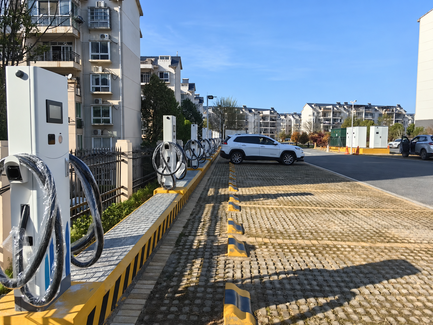
Supplied field photograph from a 480 kW split-charger project, edited to remove visible third-party branding. It illustrates site topology only; it is not evidence that the pictured project is a 350 kW system or that any outcome is universal.
Project killers: diagnose the 350 kW selection early
| Symptom | Root cause | Verify | Mitigation |
|---|---|---|---|
| The quote says 350 kW but does not state per-port output. | Rating basis is ambiguous. | Cabinet/dispenser/connector diagram and output table. | Add the exact topology to the RFQ. |
| Vehicle list contains no acceptance data. | Vehicle ceiling is assumed away. | OEM voltage/current and witnessed session case. | Build a vehicle acceptance matrix. |
| Two vehicles are expected to charge together. | Allocation policy is missing. | Equal, unequal, tapering and site-capped states. | Add concurrency cases to FAT/SAT. |
| Utility discussion begins after product selection. | Site import is treated as an installation detail. | Service, transformer, switchgear and other-load study. | Hold rating or define a staged path. |
| Liquid cooling appears as a logo-level claim. | Cooling boundary is unclear. | Cable, power electronics, alarms and derating evidence. | Request configuration-specific thermal evidence. |
| “Pass” is the entire FAT result. | Acceptance record is too weak. | Instruments, conditions, values, exceptions and sign-off. | Attach a measurable FAT/SAT protocol. |
What HG Power’s 40–480 kW portfolio statement does and does not establish
HG Power’s approved public DC portfolio context spans 40–480 kW. That is a portfolio range, not one common specification.
The reviewed CCS1 manual names ANSI-DCL120B, DCL180B, DCL240B, DCL360B and DCL480B models. It must not be used to claim that every 40–480 kW configuration shares the same connector, voltage/current range, cooling, protocol, protection, certification or concurrent-output behavior. A 350 kW requirement therefore needs its own model code, option list and evidence response.
For a configuration-specific review, request the exact model, destination, connector, vehicle set, site inputs, controls, documents and FAT/SAT conditions. Start with HG Power’s DC charger specifications and then ask for the exact configuration rather than relying on a generic power-band label.
Frequently asked questions
Does a 350 kW charger charge every EV at 350 kW?
No. The vehicle’s voltage/current request, battery state, temperature, connector/cable and charger allocation can all limit delivered power. The station rating is an available equipment envelope, not a universal session result.
How much electrical service does a 350 kW charger require?
There is no single global answer. The site study must account for input voltage, efficiency, power factor, operating cap, transformer, switchgear, other loads, utility rules and whether more than one session can overlap. Ask the supplier and electrical designer to state their exact boundary.
Is 350 kW per connector?
Not necessarily. It may be a cabinet or aggregate system rating. Require a topology drawing and a concurrent output table showing per-connector and aggregate limits.
Is a 350 kW charger faster on an 800 V vehicle?
An 800 V vehicle may use a different voltage/current combination than a 400 V vehicle, but actual power still depends on the vehicle request, charger envelope, cable and session conditions. Do not convert voltage alone into a charging-time promise.
Does every 350 kW charger need liquid-cooled cables?
Do not generalize from the power label. Ask which components are cooled, the cable/current boundary, ambient assumptions, derating behavior and the evidence for the exact configuration.
Should a depot always buy 350 kW?
No. A depot with predictable long dwell may meet its duty with a lower-power or managed configuration. A depot with short overlapping windows may evaluate a higher envelope. The duty ledger and site study decide the candidate.
Is 350 kW the same in every market?
No. Connector standards, vehicle mix, electrical rules, certificates, utility processes and communications requirements vary by destination. The quote must be market-specific.
Request a 350 kW configuration review
Send HG Power:
- destination country and responsible project party;
- vehicle makes/models, model years and connector requirements;
- energy needed by departure and usable charging windows;
- expected concurrent sessions and minimum service floor;
- site service, transformer/switchgear, other-load and operating-cap assumptions; and
- required configuration, FAT/SAT, communications and destination evidence.
Request a configuration-specific DC charger review. HG Power can then map the requirement to an exact model and evidence boundary rather than treating “350 kW” as a complete specification.
Technical review: Marvin. This guide is procurement planning guidance. Final electrical design, destination conformity, utility engagement and commissioning decisions remain with the responsible project parties.
Sources and related guides
- U.S. Department of Energy, Alternative Fuels Data Center — https://afdc.energy.gov/fuels/electricity-stations
- Welsh Government, Electric vehicle charging infrastructure procurement — https://www.gov.wales/electric-vehicle-charging-infrastructure-procurement-html
- U.S. Department of Energy, Understanding the Soft Costs of EV Charging — https://www.energy.gov/cmei/vehicles/understanding-soft-costs-ev-charging
- Infineon, Design considerations for fast DC chargers targeting 350 kW — https://www.infineon.com/dgdl/Infineon-Design_considerations_DC_chargers-ART-v01_00-EN.pdf?fileId=5546d46269e1c019016a2ab43fb22560
- IEC 61851-23:2023 — https://webstore.iec.ch/en/publication/32973
- CharIN, increasing charging currents for BEVs — https://www.charin.global/media/pages/technology/knowledge-base/6e074ab841-1615552583/charin_endorses_increasing_charging_currents_for_battery_electric_passenger_vehicles.pdf
Related HG Power guides: 120/240/480 kW power-band guide, HPC vs DC Charging, CCS Charger Buyers Guide, Fleet EV Charging.