
What Is an MCS Charger? SAE J3271 Megawatt Charging System Specs, Cost & China OEM Readiness (2026)
Specifications, site economics and supplier readiness for heavy-duty charging projects.
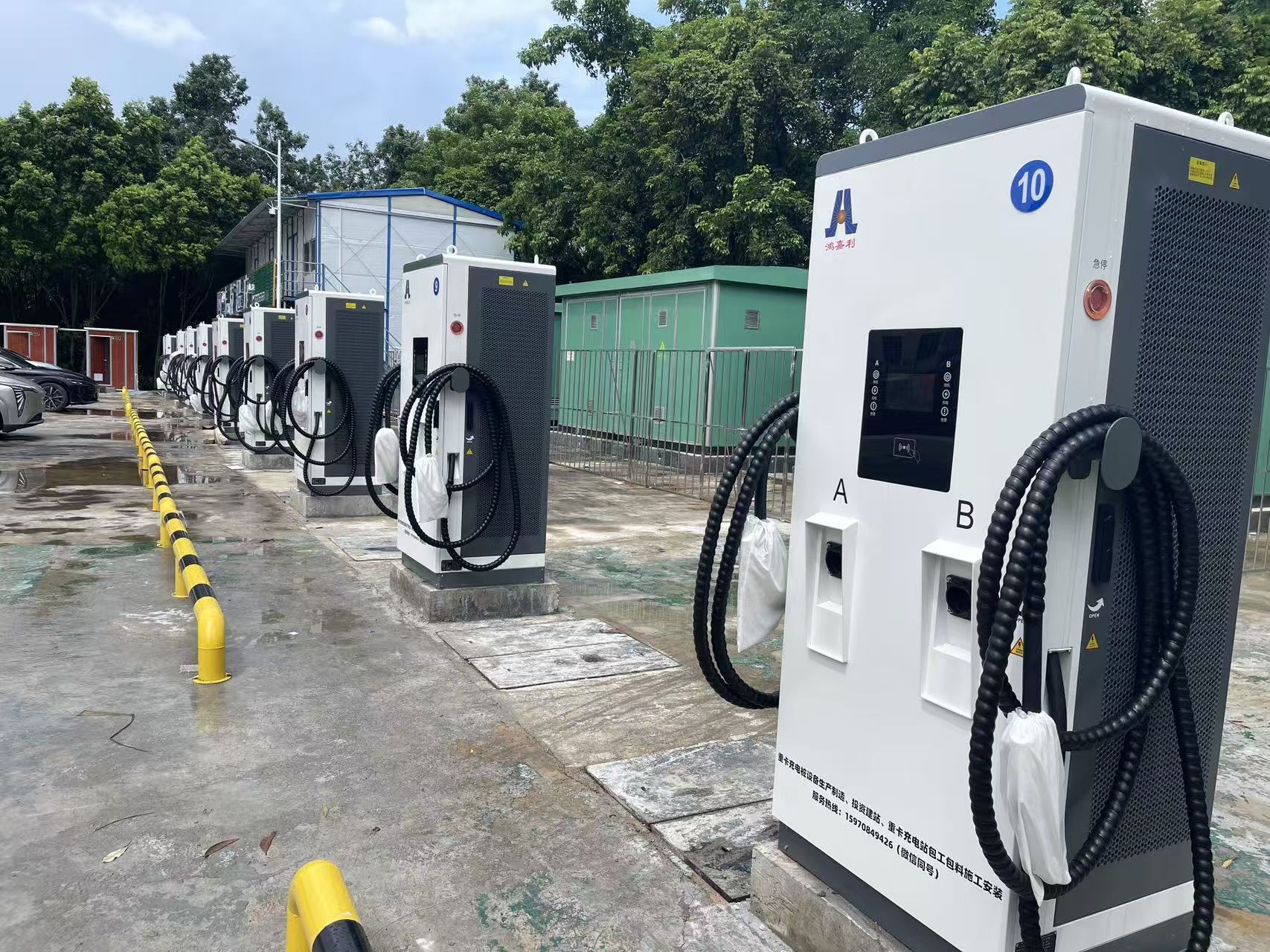
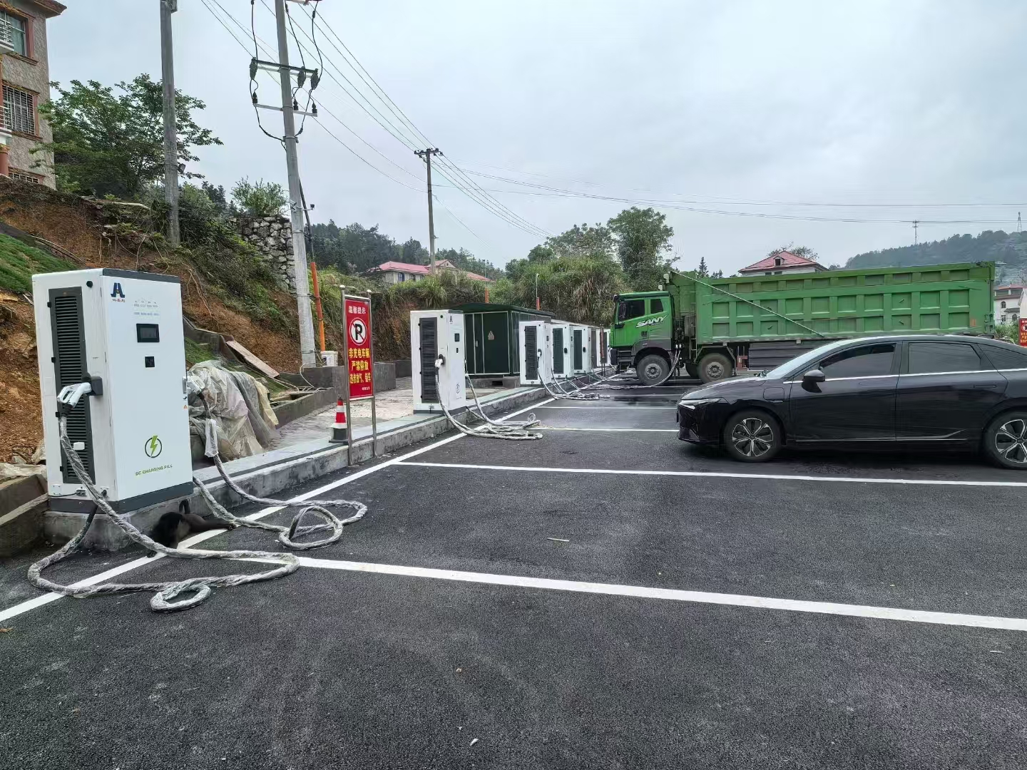
Supplied DC charging-site context; not evidence of an MCS installation.
Direct answer: The Megawatt Charging System (MCS) is a 1,250 V DC / 3,000 A / 3.75 MW fast-charging standard defined by SAE J3271 and IEC TS 63379, built on a 7-pin connector with 10BASE-T1S single-pair Ethernet and ISO 15118-20 communication for Class 7–8 heavy-duty trucks. Peak output is a 10-second specification; sustained delivery under real battery C-rate limits is typically 1.0–1.5 MW. HG Power already holds CE, TUV CB, UKCA, Australia RCM, ETL and ENERGY STAR certifications across its 30–480 kW DC range and CE on the 240–720 kW split platform (certificate CKEYS250320025) — the certified foundation for a China-built MCS adaptation with regional distributors and fleet integrators.
1. What Is an MCS Charger? SAE J3271, IEC TS 63379 and the 7-Pin Reality
In short: MCS replaces the CCS2 cable and connector with a 7-pin DC-only interface (DC+, DC−, PE, CE, ID, PHY+, PHY−) rated up to 1,250 V and 3,000 A, uses 10BASE-T1S single-pair Ethernet instead of PLC, and layers ISO 15118-20 on top for Plug & Charge, bidirectional energy transfer and smart charging authorisation.
CharIN released the first MCS Technical Specification in 2022 and the SAE J3271 Technical Information Report (TIR) was published in March 2024. The standard is organised into five sub-documents that any serious procurement specification should reference by their exact numbering.
| Sub-document | Scope | Why procurement must cite it |
|---|---|---|
| J3271/1 | Physical connector, pin geometry, mating cycles ≥ 10,000 | Determines whether a vendor’s inlet is interoperable with public hubs |
| J3271/2 | Communication & control (10BASE-T1S, ISO 15118-20) | Governs Plug & Charge and bidirectional handshake timing |
| J3271/3 | Liquid cooling and Automated Connection System (ACS) | Needed above 1.0 MW continuous — cable alone exceeds 12 kg |
| J3271/4 | Grid interconnection and V2X | Required where depot combines charging with BESS or on-site PV |
| J3271/5 | Interoperability test procedures | Written into RFQ to force vendor FAT/SAT compliance |
The 7-pin layout removes the AC pins of CCS2 — MCS is DC only. The PWM Control Pilot (CP) is also gone, replaced by a 5 V logic Charge Enable (CE) signal and a mechanical Insertion Detection (ID) latch. Communication moves to 10BASE-T1S single-pair Ethernet, which supports deterministic timing suitable for 1,500 A continuous current regulation.
| Pin | Function | Rating / signal |
|---|---|---|
| DC+ / DC− | Main power | Up to 1,250 V, 3,000 A peak / 1,500 A continuous, PT1000 inside each terminal |
| PE | Protective earth | ≥ 25 mm² cross-section, short-circuit discharge path |
| CE | Charge Enable | 5 V DC logic (replaces CCS2 PWM Control Pilot) |
| ID | Insertion Detection | Mechanical latch confirmation (replaces resistive Proximity Pilot) |
| PHY+ / PHY− | Communication | 10BASE-T1S single-pair Ethernet, ISO 15118-20 at application layer |
Framework — MCS Thermal Derating Reality Curve: 3,000 A is a 10-second peak rating. Published liquid-cooled cable qualifications settle to 1,500 A continuous under ambient 30 °C with ΔT ≤ 50 K at the terminal. Ambient 40 °C reduces coolant flow efficiency and shaves another 10–15% off continuous capability. Treat 1.0–1.5 MW as the honest sustained design point when sizing depot capacity.
2. MCS vs CCS2 for Heavy-Duty Trucks: The Dual-Gun 2×350 kW TCO Trap
In short: CCS2 ceilings out at 500 A / 1,000 V (approximately 350–400 kW continuous). A dual-gun 2 × 350 kW CCS2 configuration delivers 600–700 kW to one truck but adds a second liquid-cooled cable the driver must lift. Native MCS at 1.0–1.5 MW continuous replaces 90–120 minutes of 20→80% charging on a 600 kWh pack with 25–35 minutes using a single connector.
The temptation to postpone MCS by deploying dual-gun 2 × 350 kW CCS2 is strong — the hardware is on the shelf, the vehicles exist today, and operators avoid the “wait for the MCS ecosystem” problem. The engineering cost comes later: driver ergonomics, cable wear, and the lack of V2G support in the ISO 15118-2 stack that CCS2 shipped with.
| Metric | CCS2 350 kW single gun | CCS2 dual-gun 2×350 kW | Native MCS |
|---|---|---|---|
| Voltage ceiling | 1,000 V | 1,000 V | 1,250 V |
| Current per gun | 500 A | 500 A × 2 | 1,500 A continuous |
| Sustained power to one truck | 350–400 kW | 600–700 kW | 1.0–1.5 MW |
| 600 kWh pack, 20→80% | 90–120 min | 50–70 min | 25–35 min |
| Cable weight (operator lifts) | 6–8 kg | 6–8 kg × 2 | 12–15 kg (ACS recommended) |
| ISO 15118-20 Plug & Charge | Retrofit possible | Retrofit possible | Native |
| Bidirectional (V2G) support | Limited (ISO 15118-2) | Limited | Native (J3271/4) |
| EU AFIR 2030 TEN-T compliance | Insufficient alone | Transitional | Target standard |
For depots serving existing 400 V and 800 V trucks (350 kW DC fast chargers or dual-gun configurations) the honest answer is a mixed deployment: CCS2 for today’s fleet, MCS-ready physical infrastructure (cable runs, breaker ratings, foundations) prepared for 2027–2028 vehicle platforms. Rebuilding switchgear later costs 2–3× the upfront delta.
3. How Fast Does MCS Charge an Electric Semi? Battery C-Rate Is the Ceiling
In short: A 600 kWh LFP pack at 2C sustained accepts 1.2 MW during the flat portion of the curve and tapers above 80% SOC. “Full charge in 15 minutes” is a marketing phrase; 20→80% in 25–35 minutes is the practical operational number, and winter cold-start below −10 °C adds 8–15 minutes of preconditioning draw before current ramps.
| Chemistry | Sustained C-rate | Peak power accepted | 20→80% time at MCS | Cycle-life impact at this rate |
|---|---|---|---|---|
| LFP (prismatic, truck grade) | 2C | 1.2 MW | 30–35 min | Low; LFP tolerates fast cycling |
| NMC (truck grade) | 3C | 1.8 MW | 20–25 min | Moderate; thermal management critical |
| Next-gen high-nickel | 4C (pilot) | 2.4 MW | 15–20 min | Observable at scale; not yet standard |
Winter cold-start reality: At −20 °C ambient, a 600 kWh pack typically consumes 25–40 kWh of pack-heater energy during the first 8–15 minutes before full MCS current can be accepted. Depot operators in Scandinavia and Northeast China should budget 10–15% extra kWh throughput in Q1 energy planning.
4. Electric Semi Truck Charging Station Cost: 2026 CapEx Breakdown
In short: A 5–10 bay MCS depot in Europe runs $2.5M–$10M+ turnkey. Dispensers are 15–25% of CapEx; the MV transformer, switchgear and civil works together consume 40–55%. Chinese power-electronics supply shifts the dispenser line by 30–50% and the integrated BESS line by 20–35%, provided CE/UKCA/RCM certification is intact.
| Line item | EU Tier-1 range | China OEM reference range | Share of total |
|---|---|---|---|
| MCS dispensers (5 × 1 MW+) | $750K–$1.75M | $450K–$900K | 15–25% |
| MV transformer 5–10 MVA | $500K–$1.2M | $500K–$1.2M (local supply) | 15–20% |
| Switchgear, protection, SCADA | $400K–$900K | $400K–$900K | 10–15% |
| Civil works, foundations, trenching | $500K–$1.5M | $500K–$1.5M (local) | 15–25% |
| Grid interconnection fees | $150K–$800K | $150K–$800K (utility set) | 5–10% |
| Optional BESS 2–5 MWh buffer | $600K–$1.5M | $400K–$1.0M | 15–25% |
| Permitting, design, commissioning | $200K–$500K | $200K–$500K (local) | 5–10% |
| Total 5-bay turnkey (indicative) | $3.1M–$8.2M | $2.6M–$6.8M | — |
HG Power’s own domestic Chinese reference figures for a 2,000 kW light-storage-charging site run at approximately RMB 1.09 million CapEx with reported project IRR of 64% and simple payback near 1.73 years — numbers that reflect lower domestic civil and grid costs but validate the hardware-stack economics of the underlying 1.2 MW+ platform (station component breakdown).
CapEx comparison reviewed by Marvin Zhou (Head of International Sales, HG Power) using the HG internal 2,000 kW light-storage-charging site cost model (2026-04-25 revision) cross-checked against NREL high-power charging CapEx benchmarks.
5. 800V Heavy-Duty Truck Chargers: The Adaptive Rectifier Matrix
In short: A real depot sees 400 V legacy trucks, 800 V current-generation platforms (Scania 25P, Volvo FH Electric Gen2) and future 1,250 V MCS-native vehicles on the same site. The dispenser must adapt output voltage dynamically without stepping outside its SiC module efficiency window. The adaptive rectifier matrix determines whether one platform serves all three, or whether operators buy three sets of hardware.
| Vehicle platform | Pack voltage window | Dispenser output needed | Rectifier topology |
|---|---|---|---|
| Legacy 400 V truck (Volvo FH Gen1, Freightliner eCascadia) | 350–450 V DC | 200–500 V DC, 500–800 A | Direct DC-DC buck |
| Current 800 V truck (Scania 25P, Volvo FH Electric Gen2) | 650–850 V DC | 600–900 V DC, 1,000–1,500 A | SiC half-bridge, direct |
| Future 1,250 V MCS-native | 900–1,250 V DC | 1,000–1,250 V DC, 1,500–3,000 A | SiC full-bridge + boost stage |
HG Power’s Aurora megawatt platform operates on 10 kV medium-voltage direct input with 200–1,000 V DC output and 0–4,000 A total system current, powered by SiC modules at measured 97% efficiency on the 2.5 MW cabinet variant. The split 480 kW DCF platform and larger DCF720 variant are the certified building blocks (CE certificate CKEYS250320025) for depot-scale rollouts up to 720 kW per dispenser, with the 1.2–2.6 MW cabinets serving as the heavy-electrical foundation already operating in Chinese heavy-duty truck sites — awaiting SAE J3271 connector-and-communication adaptation for export deployment.
6. MCS vs NACS (SAE J3400) for Commercial Fleets: Why Both Appear in Depots
In short: NACS (SAE J3400) tops out around 500 A / 1,000 V with real-world sustained power of 350–500 kW — suited to Class 1–5 vehicles including delivery vans, pickups and some Class 6 regional trucks. MCS owns Class 7–8 long-haul. Mixed-fleet depots deploy both from a shared power cabinet rather than two separate systems.
| Class | Vehicle type | Best-fit standard | Why |
|---|---|---|---|
| Class 1–3 | Light delivery vans, cargo pickups | NACS or CCS2 | 150–250 kW sufficient; existing Supercharger network |
| Class 4–6 | Medium-duty box trucks, regional delivery | NACS high-power or CCS2 350 kW | 250–500 kW optimal; 2 h depot dwell acceptable |
| Class 7–8 | Heavy truck, long-haul, port drayage | MCS | 600 kWh+ packs; 45-min driver break mandates ≥ 1 MW |
In a mixed-fleet depot the sensible architecture is a common DC bus fed by one set of high-power rectifier cabinets with pluggable dispenser heads — one NACS head on the Class 1–6 side, one MCS head on the Class 7–8 side, sharing the same transformer and SCADA. This cuts the switchgear line by 30–40% versus two independent systems.
7. Export-Grade Chinese MCS Manufacturer: Readiness Checklist (and HG Power’s Position)
In short: Chinese megawatt power electronics are mature in the domestic ChaoJi / GB/T ecosystem, but public evidence of SAE J3271-native connector hardware, ISO 15118-20 stacks and complete multi-region export certifications from any single Chinese OEM is scarce. HG Power publishes its export portfolio openly: 7 out of 10 Readiness Checklist items are shipping today, 3 are on a published adaptation path for distributor and OEM partners.
Serious procurement teams score Chinese OEMs against a 10-item readiness checklist. Below is HG Power’s current position with specific certificate numbers for independent verification.
| # | Readiness item | Status | Evidence / certificate |
|---|---|---|---|
| 1 | EU CE for DC fast chargers 30–480 kW | Shipping | Certificate 3N240131.SHN0W49, DCL series |
| 2 | EU CE for split-system up to 720 kW | Shipping | Certificate CKEYS250320025, DCF240–720 series |
| 3 | UK UKCA | Shipping | Certificate CN25G3TM 001, DCL series |
| 4 | Australia RCM | Shipping | Certificate RCMC26013005D, DCL series |
| 5 | North America ETL | Shipping | Certificate 2408B2314SHA-001, ANSI-DCL030A–360B |
| 6 | US / Canada ENERGY STAR | Shipping (partial) | Certificate C2506171, ANSI-DCL240B |
| 7 | International TUV CB (IEC harmonisation) | Shipping | Certificate R 50695913 0001, DCL 30–480 kW |
| 8 | SAE J3271 native MCS connector hardware | Adaptation path | Megawatt power electronics already shipping domestically at 1.2–2.6 MW; connector integration co-developed with partners |
| 9 | ISO 15118-20 Plug & Charge stack | Adaptation path | Firmware integration scope defined; partner-driven validation |
| 10 | FAT/SAT with bilingual (CN/EN) RFQ, documentation and acceptance protocols | Shipping | Current export process covers full test suite and documentation |
HG Power manufactures 30–720 kW DC fast chargers and AC wallboxes with CE, TUV CB, UKCA, Australia RCM, ETL and ENERGY STAR certifications for regional distributors, fleet integrators and OEM buyers in developed markets. The 1.2–2.6 MW platform ships today in Chinese heavy-duty truck depots and provides the SiC-based power stage on which a J3271-native MCS variant can be assembled with distributor partners who need predictable 8–12 week lead times, bilingual RFQ response and on-site factory audit access.
8. MCS Deployment Timeline 2024–2030: AFIR, Milence and the Grid Queue Reality
In short: EU AFIR Regulation 2023/1804 mandates heavy-duty charging on TEN-T core corridors every 60 km by 2030. Milence targets 90 hubs and 300+ MCS terminals by 2028. The real bottleneck is grid interconnection queues of 24–36 months — making BESS buffering not optional but structural for 2026–2028 projects.
| Period | Milestone | Significance for buyers |
|---|---|---|
| 2022 | CharIN MCS Technical Specification v1 released | Interface geometry frozen for connector tooling |
| 2024 Q1 | SAE J3271 TIR published | North American regulatory anchor established |
| 2024–2025 | HoLa corridor Germany, Milence Landvetter & Antwerp pilots | First 1.2–1.4 MW public-access points live |
| 2026 | Milence > 30 operational sites, four-OEM interop tests | Small-batch commercial deployment window |
| 2028 | Milence 90 hubs, 300+ MCS terminals targeted | Commercial scale; procurement decisions must be placed by 2026 Q4 |
| 2030 | EU AFIR TEN-T mandate deadline | > 50% of HDT charging terminals must be ≥ 1 MW |
Grid queue reality: In Germany, Netherlands and parts of the UK, utility interconnection for new 5–10 MVA depot loads is quoted at 24–36 months. The functional workaround is a BESS buffer sized to peak-shave the depot load: a 2–5 MWh battery charged during off-peak enables 1–2 MW continuous charging on an existing 1–2 MVA grid connection, letting the depot begin revenue 18–24 months before full grid upgrade. HG Power’s domestic 2,000 kW light-storage-charging reference configuration (RMB 1.09M CapEx, 64% IRR, payback 1.73 years) is the engineering template.
9. Common Mistakes When Specifying MCS Infrastructure
We get these questions and corrections across RFQs every month. Five patterns show up repeatedly.
- Sizing dispensers to peak 3.75 MW rather than sustained 1.5 MW. We flag this on first conversation — the number controls your transformer, cable runs and whole-of-site CapEx. Sizing to peak over-builds switchgear by 30–40%.
- Treating MCS and NACS as mutually exclusive. Mixed fleets exist; the common-DC-bus architecture (section 6) shares rectifier cabinets across both dispenser types. We help buyers lay out the topology before cable-trench procurement is locked.
- Skipping ISO 15118-20 provisioning in year-1 scope. Buyers assume firmware upgrades close the gap later. In practice, PKI certificate infrastructure and backend contract-id handling must be in the deployment plan from day one, or Plug & Charge rollout slips by 12 months.
- Ignoring the BESS buffer as structural rather than optional. We get asked whether the BESS line is “nice to have” when quoting on 24-month grid queues. It is the only way to open the depot before full interconnection; the economic model assumes it exists.
- Buying on dispenser price per kW alone. Multi-region certification bodies (CE / TUV CB / UKCA / RCM / ETL) move with vehicle certification cycles; a dispenser without them cannot be commissioned on the depot the day the trucks arrive. We publish our certificate numbers so RFQ teams can verify independently before paying.
10. Frequently Asked Questions
Q1. Is MCS compatible with existing CCS2 chargers?
No. MCS uses a different connector (7-pin DC-only), different communication layer (10BASE-T1S Ethernet replacing PWM), and higher voltage/current ceiling (1,250 V / 3,000 A versus 1,000 V / 500 A). Dual-standard dispensers are possible with two separate heads sharing a common rectifier cabinet, but a CCS2 cable cannot be used on an MCS vehicle inlet.
Q2. Will Tesla Semi adopt MCS?
Tesla’s current Megacharger is a proprietary interface. CharIN has publicly stated MCS is the open standard it recommends for Class 7–8 trucking, and SAE J3271 is now a published TIR. Tesla has not publicly confirmed a Megacharger-to-MCS migration, though adapters and dual-head site deployments remain the most likely transition path for mixed fleets.
Q3. Can a passenger car with an 800 V system plug into an MCS charger?
No. MCS uses a physically different connector sized for 3,000 A liquid-cooled cable. Even if a mechanical adapter were produced, a passenger-vehicle battery (typically 80–120 kWh at 2–4 C acceptance) could not use MCS’s power envelope, and the mating cycle rating is sized for commercial-vehicle duty.
Q4. What is the lead time for a Chinese-manufactured MCS or megawatt charger with CE and UKCA?
For HG Power’s CE-certified DCF 240–720 kW split platform, standard RFQ response is within 5 working days and factory lead time is 8–12 weeks after order confirmation. For 1.2 MW+ megawatt variants with MCS connector adaptation, the engineering scope is co-defined per project and lead time is set jointly with distributor or OEM partners.
Q5. How does the EU AFIR regulation affect MCS procurement decisions?
EU Regulation 2023/1804 requires operators of the TEN-T core road network to provide heavy-duty vehicle charging stations at least every 60 km by 31 December 2030, with ≥ 1,400 kW aggregated power per station and at least one ≥ 350 kW individual charging point. For long-haul corridors, meeting this with CCS2 alone requires more terminals and more land per site than an MCS-based deployment.
Q6. Does an MCS dispenser require automated connection (robotic plug)?
SAE J3271/3 covers the Automated Connection System (ACS) option. It is not mandatory, but above approximately 1.0 MW continuous the liquid-cooled cable weight exceeds 12 kg and ergonomic standards in several jurisdictions make ACS the practical choice for depot operations. Driver-plug operation remains viable for sites running occasional top-up charging rather than continuous turnover.
Name: Marvin Zhou
Role: Head of International Sales, HG Power
Brand: HG Power (Hongjiali New Energy)
Website: hongjialicharge.com
WhatsApp: +86 189 2467 8741
Email: marketing@hjlcharger.com
Partnership: Partner with HG Power
References
- CharIN e.V. — Megawatt Charging System technology page. charin.global/technology/mcs/
- SAE International — J3271 Technical Information Report. sae.org/standards/content/j3271_202403/
- IEC TS 63379 — Megawatt charging system for electrically propelled road vehicles. webstore.iec.ch
- EU Regulation 2023/1804 (AFIR) — Alternative Fuels Infrastructure Regulation. eur-lex.europa.eu
- NREL — High-Power Charging Research. nrel.gov/transportation/high-power-charging.html
- Milence — Public MCS deployment roadmap and press releases. milence.com/newsroom/
- ICCT — Zero-emission heavy-duty vehicle working papers. theicct.org
Why I write this: HG Power manufactures 30–720 kW DC fast chargers and AC wallboxes with CE, TUV CB, UKCA, Australia RCM, ETL and ENERGY STAR certifications for regional distributors, fleet integrators and OEM buyers in developed markets. MCS is where the next decade of heavy-duty transport electrification is being decided, and the public conversation is dominated by standard bodies and project operators — the supply-side evidence from Chinese manufacturers that could partner on real export deployments is almost absent. I write this to publish our certificate numbers, our honest readiness position, and the engineering reality that separates marketing peak-power claims from sustained-power procurement decisions.
Chat on WhatsApp: +86 189 2467 8741 or write to marketing@hjlcharger.com. We respond to RFQs within 5 working days with power sizing, certificate copies, FAT/SAT scope and bilingual documentation.