
What Is a DC Charging Pile? EV Charger, Cabinet, Dispenser and Station Explained
Translate “charging pile” into an exact DC equipment boundary before comparing suppliers, power ratings or station architectures.
Direct answer: “Charging pile” is a widely used market term for EV charging equipment, especially in Chinese and Asian supplier documentation. In an international DC procurement brief, translate it into a precise boundary: AC input, DC output, power rating, connector, cabinet/dispenser architecture, vehicle communication, site power-sharing and backend scope. A 120 kW charging pile is not a complete specification until those interfaces and the exact model are named.
Start with the translation, not the label
| Term seen in a quotation | Usually points to | What the buyer must still define |
|---|---|---|
| Charging pile | One charging device or post; usage varies by market | AC/DC, output, connectors, enclosure, cabinet and dispenser relationship |
| DC charger | Equipment that converts site AC to controlled DC for the vehicle | Voltage/current envelope, power modules, cooling, communication and protection |
| EVSE / charge point | The equipment and safety/control interface that enables charging | Electrical architecture, connector, backend and destination approvals |
| Power cabinet | Centralized rectifiers and controls in a split system | Number of dispensers, cable route, sharing logic, service access and expansion |
| Dispenser | User-facing vehicle connection point, sometimes remote from cabinet | Per-connector output, cable length, screen/payment, emergency controls |
| Charging station | Site-level arrangement of one or more charge points | Utility, civil works, access, operations, payment, networking and acceptance |
The terms overlap in everyday sales language. That is why an international buyer should keep the supplier's original term for search and conversation, then rewrite it into the equipment boundary used in the purchase order.
The Translation Ladder
Move through four levels before comparing quotations:
- Market phrase: “new energy charging pile” or “120 kW DC pile.”
- Equipment boundary: all-in-one DC post, split power cabinet plus dispenser, or another defined architecture.
- Technical envelope: input, DC voltage/current, power-sharing, connector and control interfaces.
- Acceptance scope: documents, FAT, site readiness, SAT, backend tests and handover records.
If a quotation stops at level one, it is not yet comparable. The phrase may be useful for finding suppliers, but it is not a model specification.
What does a DC charging pile do?
In AC charging, the vehicle generally performs the AC-to-DC conversion through its onboard charger. A DC charging system places the controlled conversion equipment outside the vehicle and supplies DC through the vehicle-side DC interface. The vehicle still controls and protects the charging session through its communication and battery-management logic. The US Department of Energy describes this AC/DC boundary and warns that delivered power can vary with the vehicle and equipment.
For a commercial buyer, the important consequence is not simply “DC is faster.” It is that the charging pile becomes a power-conversion, control, thermal, safety and service system that must match the vehicle and site.
The Five-Layer DC Chain
All-in-one pile or cabinet-and-dispenser system?
| Architecture | Where conversion hardware sits | Useful when | Questions to resolve |
|---|---|---|---|
| All-in-one DC charger | Power electronics and user interface share one enclosure | Shorter cable routes, compact sites or simpler single-unit deployments fit | Service clearance, acoustic/thermal behavior, connector reach, expansion and site footprint |
| Split cabinet + dispenser | Shared rectifiers sit in a cabinet; one or more dispensers serve bays | A hub needs power sharing, multiple bays, staged expansion or remote dispensers | Cabinet-to-dispenser DC route, per-port ceiling, allocation logic, isolation and fault behavior |
| Modular multi-cabinet system | Multiple power blocks coordinate across a larger site | Capacity and redundancy need to grow in stages | Module failure policy, common controls, synchronisation, maintenance and acceptance boundary |
Do not assume that a remote dispenser has the same practical output as the cabinet nameplate. Cable length, connector limits, simultaneous sessions, thermal conditions and the configured allocation can become the active ceiling.
Five questions behind every DC power label
| Label in the request | Procurement question | Required evidence |
|---|---|---|
| 40–480 kW | Is this a portfolio range or the exact offered model? | Model code, datasheet revision and quotation |
| 120 kW | Is power per cabinet, per connector or shared across outputs? | Allocation table at one, two and full occupancy |
| 1000 V | Is it the maximum DC voltage, operating range or vehicle-side limit? | Electrical envelope and vehicle compatibility matrix |
| 500 A | Is current continuous, peak, liquid-cooled or connector-specific? | Connector/cable rating, thermal conditions and test method |
| Dual gun | Can both vehicles charge simultaneously, and at what allocation? | A/B concurrency and recovery test cases |
HG Power's approved public DC portfolio is 40–480 kW. A reviewed CCS1 manual covers named 120/180/240/360/480 kW models. Those statements must remain separate: the manual does not automatically establish the specifications of 40/60 kW products, another connector family or every destination-market configuration.
Connector is an interface decision, not a complete product definition
Name the vehicle-side interface and market: CCS1, CCS2, CHAdeMO, GB/T, NACS or another approved path. Then define cable arrangement, connector count, locking, thermal management, communication and the vehicle population.
The same cabinet concept may require different connector and certification packages by destination. Use the CCS charger buyer's guide, CHAdeMO compatibility guide or HPC vs DC guide for those narrower decisions.
Site power and sharing decide what a pile can deliver
Record service voltage, phase, transformer capacity, spare capacity, demand limit, feeder length, simultaneous vehicle count and expansion plan. Then request an allocation schedule showing single-session, partial-occupancy and full-occupancy behavior.
Cabinet nameplate → site delivery
→
→
→
Every arrow is a verification boundary. A nameplate alone is not delivered energy.
Ask how the system behaves when the meter, network, controller or one power module is unavailable. A useful quotation includes fail-safe behavior, minimum allocation, session recovery and event records rather than only the maximum kW.
OCPP belongs to the operations layer
OCPP is a communication protocol between charging stations and central systems. The Open Charge Alliance maintains version-specific capabilities, including OCPP 1.6, 2.0.1 and 2.1. “OCPP supported” should therefore be rewritten as exact version, tested functions, transport, firmware and backend relationship.
The RFQ should name authorization, transaction records, meter values, remote reset, availability, offline operation, smart charging, firmware updates, security credentials and data export. OCPP does not by itself prove the charger’s DC output, connector certification or local electrical compliance.
Cabinet, dispenser and station RFQ matrix
| Input | Decision | What fails without it | Required deliverable |
|---|---|---|---|
| Vehicle list and connector | CCS1/CCS2/CHAdeMO/GB/T/NACS path | Incompatible or unusable sessions | Vehicle-interface matrix |
| Target power and concurrency | per-port vs aggregate allocation | Nameplate exceeds usable site output | A/B/full-occupancy schedule |
| Site supply | input voltage, phase, transformer and demand | Service upgrade or recurring curtailment | One-line diagram and load study |
| Cabinet/dispenser layout | all-in-one or split architecture | Long routes, poor service access or blocked bays | Dimensioned layout and cable route |
| Thermal environment | air/liquid cooling and ambient conditions | Derating, connector limits or maintenance burden | Thermal envelope and test conditions |
| Backend | OCPP version and CSMS | Demo works but operations fail | Interoperability test matrix |
| Acceptance | FAT, SAT and handover evidence | No objective release decision | Named test cases and records |
Project-killer diagnostic table
| Symptom | Likely boundary failure | Verify | Corrective direction |
|---|---|---|---|
| “120 kW” never reaches one vehicle | vehicle, connector or shared allocation ceiling | vehicle request, voltage/current, occupancy and logs | Match exact vehicle and allocation; do not simply increase nameplate |
| One dispenser works, two do not | cabinet-to-port sharing or site capacity | A/B/full-load tests | revise power modules, site allocation or port plan |
| Cabinet is accepted but bays are unusable | dispenser route, cable reach or civil layout | full vehicle sweep and maintenance access | relocate dispenser/cable route and retest |
| OCPP demo works but records are incomplete | version/profile/backend mismatch | offline, reset, transaction and meter-value tests | freeze versions and run interoperability FAT/SAT |
| Supplier quotes “new energy charger” only | equipment boundary is undefined | request model, architecture and document list | convert phrase through the Translation Ladder |
HG Power evidence and scope
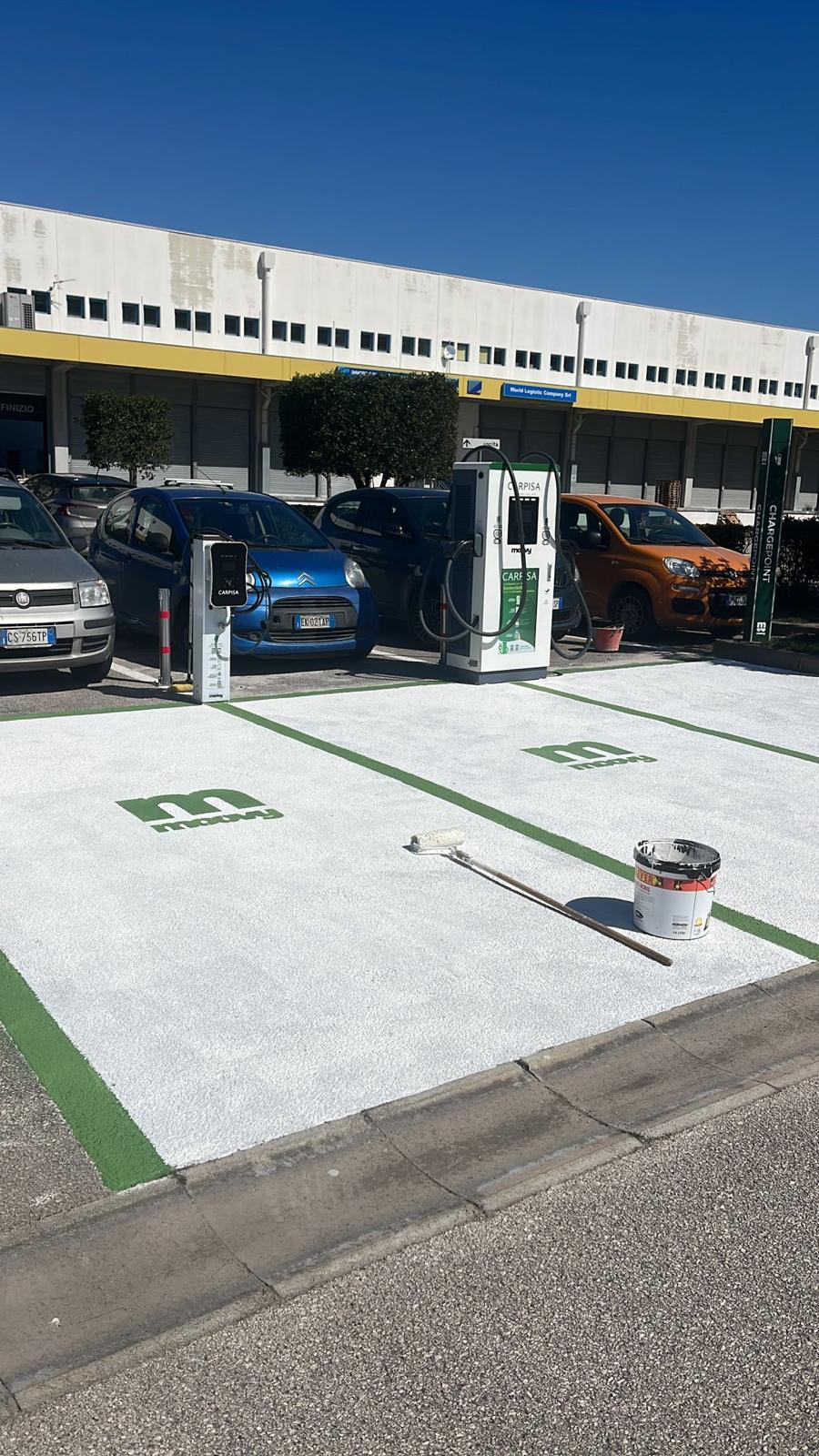
HG Power's public DC portfolio is 40–480 kW. Exact connector, voltage/current envelope, power-sharing, cooling, protection, protocol, certificate and destination documentation remain model- and project-specific. The supplied DC product image in this guide is product-context evidence only; it does not prove a particular output, certification or field result.
For the station-engineering workflow, use the DC fast charger station design guide. For supplier evidence, use the EV charger supplier qualification guide. For cost boundaries, use the commercial DC fast charger cost guide.
FAT and SAT: make the pile observable
At minimum, a commercial DC charging-pile acceptance pack should identify the exact model and revision, input/output envelope, connector, protection, display and emergency controls, communication version, power-sharing states, normal charging, concurrent charging, interrupted charging, fault recovery, meter records and handover documents. The exact tests depend on destination, vehicle and contract.
Frequently asked questions
Is a charging pile the same as an EV charger?
Often the terms overlap in supplier language, but “charging pile” is not a sufficiently precise international purchase specification. State whether the equipment is AC or DC, all-in-one or split, its output and connector, and what site/backend scope is included.
What is a DC charging pile?
It is a market term for DC charging equipment that converts site power into controlled DC for an EV through a defined vehicle interface. The exact architecture may be an all-in-one charger or a cabinet feeding one or more dispensers.
Does 480 kW mean one car receives 480 kW?
Not automatically. It may describe a cabinet or system maximum. Vehicle acceptance, connector/cable limits, temperature, power sharing and site allocation can all produce a lower session value.
Is OCPP part of the charger hardware?
OCPP is a communication protocol used between a charging station and a central system. It is an operations interface, not a substitute for electrical, connector or certification specifications.
What should I send for a DC charging-pile quotation?
Send destination, vehicle/connector list, target power, concurrent sessions, site voltage/phase/capacity, cabinet/dispenser preference, cable routes, cooling/environment, backend, documents and required FAT/SAT cases.
Request a configuration review
If a supplier request says only “new energy charging pile” or “120 kW DC charger,” send the phrase together with the vehicle list, destination, connector, power-sharing requirement, site input and acceptance expectations. HG Power can then convert it into an exact model and evidence matrix rather than comparing ambiguous labels.
Technical reviewer: Marvin
Last reviewed: September 22, 2026