
22kW EV Charger Cable Size: A 32A Three-Phase Design Guide
Start at 32A per phase—then prove corrected ampacity, voltage drop, protection, fault performance and the exact EVSE interface.
A nominal 22kW AC charger is commonly a 400V three-phase, 32A-per-phase load. But 32A is only the first input. The final supply-cable size depends on the exact charger, local grid and rules, conductor and insulation, installation method, ambient temperature, grouping, route length, voltage drop, protective device and fault conditions.
Quick answer: For a 22kW, 400V, three-phase EVSE, the calculated current is about 31.8A per phase at a power factor of 1. A 6mm² copper conductor is a common candidate in some installation tables and product manuals, but it is not a universal answer. The selected cable must pass corrected current-carrying-capacity, voltage-drop, protection/fault and equipment-terminal checks under the destination's rules. A qualified local electrical designer or installer must make and verify that selection.
Reviewed by Marvin · Technical guide · Updated September 2026
First, which “EV charger cable” do you mean?
The search phrase hides two different products:
- The fixed supply cable runs from a distribution board or local panel to the EV supply equipment (EVSE). Its conductor size is part of the building's electrical design.
- The vehicle charging cable runs from the EVSE to the vehicle inlet. It may be tethered to the charger or detachable. It is a purpose-built assembly with a rated current, connector, temperature behavior and cable length.
This guide addresses the fixed supply circuit. Do not use a building-cable calculation to manufacture, extend or replace the vehicle charging lead. The IET also notes that the supply cable and charging lead contribute separately to the voltage available at the vehicle interface.
Why 22kW normally points to three-phase 32A
For balanced three-phase AC, a useful first calculation is:
I = P / (√3 × VLL × power factor)
If the assumed power factor is 1.00:
| Nominal line-to-line voltage | Calculation | Current per phase |
|---|---|---|
| 380V | 22,000 ÷ (√3 × 380) | 33.4A |
| 400V | 22,000 ÷ (√3 × 400) | 31.8A |
| 415V | 22,000 ÷ (√3 × 415) | 30.6A |
That is why many IEC-market 22kW AC EVSE configurations are described as three-phase, 32A. An official DEFA product example, for instance, specifies up to 22kW, adjustable 6–32A and a 380–420Vac three-phase input. HG Power's internal product register likewise records named IEC-oriented 22kW variants on a three-phase, 32A path.
The equation is a reasonableness check—not a substitute for the nameplate. A charger may be limited or configured below its maximum, and its input specification may include tolerances, standby loads or installation requirements not captured by the simple equation.
A “22kW single-phase” assumption leads to a very different current: about 95.7A at 230V before other considerations. That contrast is enough to show why power alone cannot identify a cable.
A cable size is the output of six passed checks
→
→
→
→
→
Fail one check and the cable system—or the route—must change.
The six-check proof for a 22kW supply cable
A safe cable schedule needs six checks. If any one fails, the section or cable system must change.
1. Lock the exact EVSE and supply
Record the charger manufacturer, model, hardware revision and configured maximum current. Then record:
- destination country and governing electrical rules;
- nominal voltage, phase arrangement and frequency;
- earthing/supply system;
- available fault level and the supplying board;
- whether a neutral is required by the exact EVSE;
- terminal conductor material, cross-section range and temperature rating; and
- manufacturer requirements for upstream protection and residual-current protection.
“22kW charger” is not an adequate specification. A European three-phase product, a North American product and a locally reconfigured unit can have different input, terminal and documentation paths even when a marketing page places them in the same power family.
2. Establish design current
Use the manufacturer's maximum input current or the configured current permitted by its instructions—not just a number reverse-calculated from rounded kW.
For a typical 400V three-phase unit, approximately 32A per phase is a useful planning value. But the design must also determine how the jurisdiction treats an EV charging load, whether a continuous-load multiplier applies, and whether an approved load-management limit may be used. These are local design questions, not global constants.
For a single circuit, the familiar coordination logic is that the load current, protective-device rating and corrected cable capacity must be mutually compatible. The exact symbols and requirements vary by code, but the practical question is constant: can this cable carry the permitted load after every applicable correction, while the protective device still protects it?
3. Calculate corrected current-carrying capacity
The printed ampacity for a conductor is rarely the final ampacity. The cable table must match the actual system:
- copper or aluminium conductor;
- conductor and cable construction;
- PVC, XLPE or other insulation temperature class;
- number of loaded conductors;
- single-core or multicore arrangement;
- clipped/direct, cable tray, conduit, trunking, wall, thermal insulation, buried duct or direct-buried route;
- air or soil temperature and, where relevant, soil thermal resistivity;
- grouping with other loaded circuits;
- enclosure, sunlight and local heat sources; and
- harmonic-current and neutral-loading conditions where applicable.
The IEC-based Schneider Electric guide treats these as correction factors applied to the tabulated current-carrying capacity. The corrected result—not the unadjusted catalog number—must cover the design and protection conditions.
This is the central weakness of “22kW = 6mm²” charts. Six square millimetres may pass one reference method at one temperature and fail another after thermal insulation, grouping or a hot route is considered.
4. Check voltage drop independently
A cable can be thermally adequate and still have excessive voltage drop. Longer routes increase conductor impedance; higher current increases the drop. The designer must compare the complete circuit with the applicable national limit, the EVSE's permitted input range and the project's efficiency/operating objective.
For a balanced three-phase circuit, a common engineering form is:
ΔV = √3 × I × (R cosφ + X sinφ) × L
where R and X are conductor resistance and reactance per unit length, and L is the one-way route length in the same length unit. Cable manufacturers and national tables may instead provide a millivolt-per-ampere-per-metre value. Use the method required for the project and the appropriate operating temperature.
Do not forget the system boundary. The fixed supply cable is not the only impedance between the source and the vehicle. Connections, distribution conductors and the EV charging lead can consume part of the available voltage-drop budget.
5. Coordinate protection, earthing and fault performance
Conductor selection must be coordinated with:
- overload and short-circuit protection;
- fault-loop or automatic-disconnection requirements;
- protective conductor sizing;
- residual-current protection and any DC residual-current detection inside the exact EVSE;
- surge protection where required;
- isolation and switching;
- the site's earthing arrangement; and
- selectivity with upstream devices where the project requires it.
It is unsafe to copy a breaker or RCD line from another charger manual. The correct arrangement depends on the equipment's integrated protection, the supply system and local rules. IEC 60364-7-722 addresses EV-supply circuits, while the product's IEC 61851 documentation and installation instructions define the equipment interface. Neither removes the need for a destination-specific design.
6. Check physical interfaces and prove the installation
An electrically calculated conductor can still be unusable if it does not fit the EVSE terminal or cable gland. Confirm:
- acceptable conductor material and class;
- terminal minimum/maximum cross-section;
- ferrule or lug requirements;
- gland and overall cable-diameter range;
- bending radius and entry direction;
- tightening method/torque from the exact manual;
- enclosure rating after entry; and
- space for safe termination and maintenance.
Commissioning then has to verify the installed circuit under local rules and the EVSE manufacturer's procedure. The project record should identify the as-built cable, route, protective devices, settings, inspection/test results and responsible parties.
So, can 6mm² supply a 22kW EV charger?
Sometimes it may be a valid candidate; sometimes it is not. A useful answer has to state the conditions.
Six square millimetres of copper appears in many 22kW search results because the underlying load is often around 32A per phase and some common installation tables provide sufficient nominal capacity. Yet the same conductor can become unsuitable when:
- it passes through thermal insulation or a high-temperature area;
- multiple charger circuits are grouped;
- a buried duct has poor thermal conditions;
- the route is long enough for voltage drop to control the design;
- the protective-device arrangement requires a different capacity;
- fault performance is inadequate;
- the selected cable construction/table differs; or
- the local code or exact EVSE instructions require another solution.
Conversely, choosing a larger conductor by habit is not the entire design. The larger conductor still has to fit the charger terminal and gland, bend safely, coordinate with the protection and meet the project's installation rules.
Same 32A load, same 30m route, different resistive drop
400V three-phase · PF≈1 · copper R≈23.7/S Ω/km · reactance, joints and upstream drop excluded. Ampacity, fault, protection, terminals and code are not assessed here.
A transparent 30m voltage-drop illustration
The following comparison is only a voltage-drop illustration, not a cable recommendation.
Assumptions:
- 400V balanced three-phase supply;
- 32A per phase;
- 30m one-way route;
- copper conductors;
- power factor approximately 1;
- resistance approximation
R = 23.7/S Ω/kmfrom the cited Schneider guide; - reactance, connections and upstream drop omitted.
| Conductor cross-section | Approx. resistance | Calculated drop | Percentage of 400V |
|---|---|---|---|
| 6mm² | 3.95Ω/km | 6.57V | 1.64% |
| 10mm² | 2.37Ω/km | 3.94V | 0.99% |
The larger conductor reduces resistive voltage drop in this fixed example. The table does not show whether either conductor passes corrected ampacity, protective-device, short-circuit, earth-fault, terminal or local-code checks. A designer should use the actual cable manufacturer's data or the mandated national method rather than treating this simplified arithmetic as final design software.
One 32A load, four routes—and four possible outcomes
The quickest way to understand cable sizing is to keep the charger load constant and change the route.
| Route scenario | What changes | Likely controlling checks |
|---|---|---|
| Short, ventilated tray route | Free-air heat dissipation; limited grouping | Exact reference method, terminal fit, protection and normal voltage drop |
| Buried duct to an outdoor pedestal | Soil/duct thermal conditions, water/mechanical exposure, pulling and gland constraints | Corrected ampacity, cable construction, route protection and fault performance |
| Indoor garage with many parallel EV circuits | Repeated loaded cables, trays/conduits, local temperature and future circuits | Grouping correction, diversity/load management, enclosure temperature and maintainability |
| Long run to a remote parking area | Impedance and project-wide voltage-drop budget increase | Voltage drop, conductor economics, distribution architecture and fault performance |
No row supplies a universal cross-section because that is the lesson: the route is part of the electrical load specification.
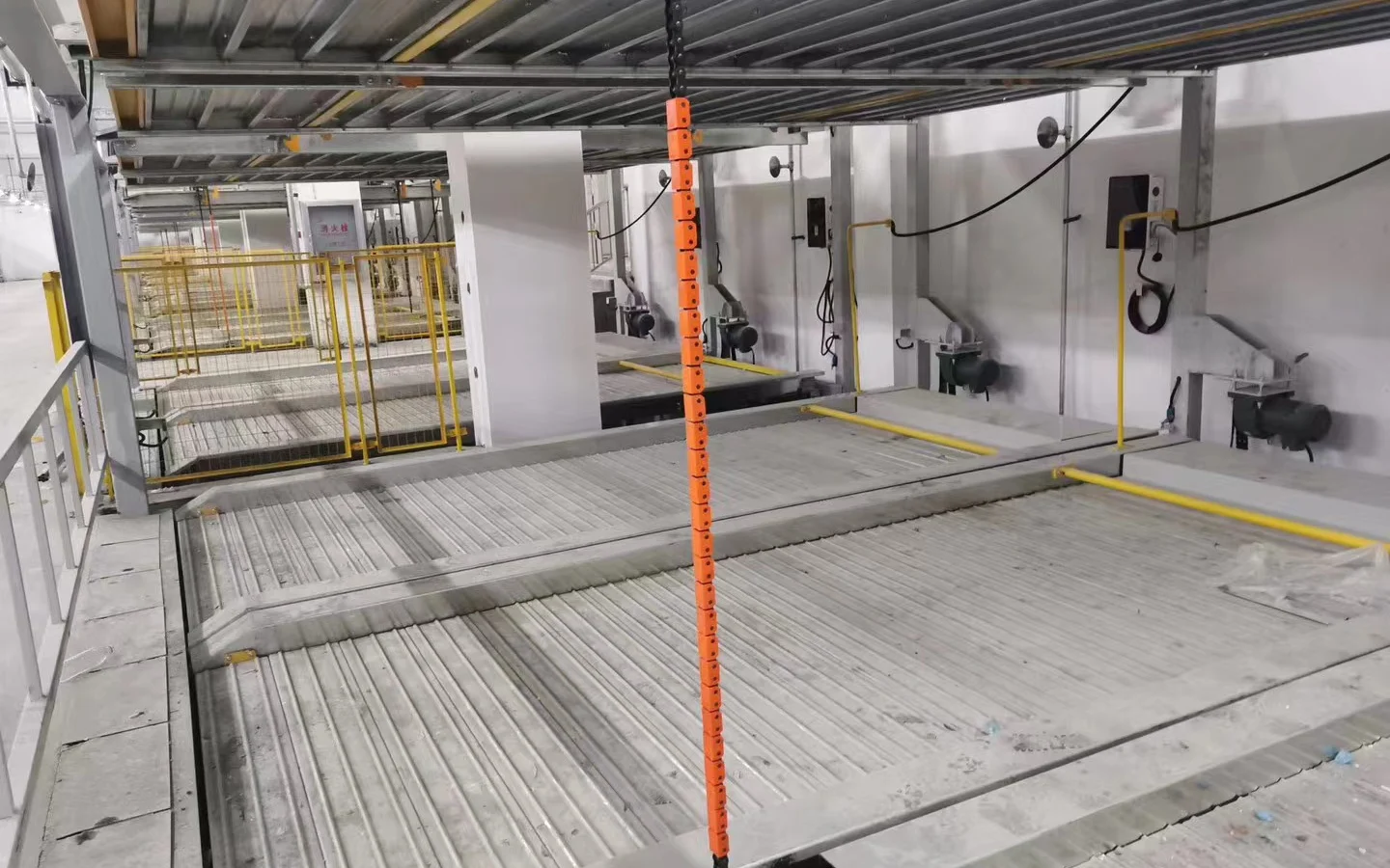
Real HG Power project imagery makes the difference visible. Repeated wall units in an indoor parking facility raise grouping and distribution questions. Mechanical parking introduces structure, clearance, movement and protected-routing constraints. These photos are not evidence that a pictured unit is 22kW or uses a particular cable; they are evidence that cable selection cannot be detached from the site.
Copper or aluminium? PVC or XLPE? How many cores?
These are not interchangeable labels.
Conductor material
Aluminium has higher resistance than copper for the same cross-sectional area. The Schneider calculation reference uses approximately 23.7/S Ω/km for copper and 37.6/S Ω/km for aluminium in its stated context. Aluminium may be commercially attractive on larger feeders, but it changes cross-section, terminals/lugs, jointing practice, corrosion controls and installation requirements. Never assume an EVSE terminal accepts it directly.
Insulation and cable construction
PVC and XLPE cable tables can permit different operating temperatures and current-carrying capacities, but the installation cannot be selected by temperature rating alone. Equipment terminals, glands, environmental exposure, fire performance and national cable rules all remain part of the design.
Core count and neutral
A three-phase EVSE supply often includes three line conductors and protective earth, and many products also require a neutral for internal loads or a particular supply arrangement. That does not justify a universal “five-core” rule. Confirm the exact wiring diagram, earthing system and local requirements. Protective-conductor sizing must also be calculated or selected under the applicable rule; it is not simply a casual add-on to the phase conductor choice.
What changes when the site has several 22kW chargers?
Multiplying 32A by the port count is a useful worst-case screening calculation, but it is not a complete distribution design.
The project needs to distinguish:
- each final circuit to an EVSE;
- shared distribution boards and submains;
- the maximum permitted site demand;
- static or dynamic load management;
- minimum charging service promised to users;
- loss-of-communications behavior;
- phase balancing; and
- future expansion.
Managed charging may limit coincident demand, but only an approved architecture and defined fail-safe state can support the design. Do not reduce feeder or final-circuit capacity based on an assumed software behavior that is absent from the design documents and acceptance test.
For deciding whether 7, 11 or 22kW fits vehicle dwell time and onboard AC acceptance, use the commercial Level 2 EV charger guide. This cable page begins after the operating power and exact model path have been selected.
The HG Power product-interface boundary
HG Power's current internal product documentation includes 7–22kW wall/column AC families, with named IEC-oriented 22kW variants following three-phase/32A paths. That is sufficient to begin a project discussion, but not to publish one global supply-cable size.
For a quotation, request the exact model's electrical interface pack and verify at least:
- rated/configured input voltage, phases, frequency and maximum current;
- whether neutral is required;
- terminal material and conductor cross-section range;
- cable-entry/gland limits;
- integrated residual-current and other protection functions;
- required upstream protective devices;
- environmental and enclosure constraints;
- connector/tethered-cable configuration;
- model-specific declaration, certificate and report scope; and
- installation, commissioning and maintenance documents.
The available 11/22kW compliance file set is not used here to make a broad certification claim because one annex requires clarification. Destination acceptance must always be checked against the exact quoted model and current documents.
Do not price the circuit until these four blocks are complete
The 14 inputs for a cable schedule or RFQ
Send these inputs to the qualified local designer and EVSE supplier before anyone prices the final circuit:
- destination country, site address and governing electrical standard;
- supply system, nominal voltage, phases and frequency;
- earthing arrangement and available fault data;
- charger manufacturer, exact model/revision and data sheet;
- maximum configured input current and load-management rules;
- neutral and protective-conductor requirements;
- conductor material and permitted cable family;
- one-way route length;
- installation method for every route segment;
- ambient/soil conditions and thermal resistivity where relevant;
- grouping, enclosure and nearby heat-source conditions;
- project voltage-drop limit and upstream drop already allocated;
- protective-device, RCD/DC-detection and surge-protection concept; and
- terminal/gland limits plus commissioning and as-built deliverables.
If the route changes, the cable calculation may change. Put route assumptions on the drawing and cable schedule rather than burying them in an email.
Common mistakes to remove before procurement
Mistake 1: selecting by kW alone
Power does not reveal voltage, phase or current. Begin with the exact nameplate and supply.
Mistake 2: copying the first 6mm² answer
A cross-section without a cable type, installation method and correction factors is not a design.
Mistake 3: checking ampacity but not voltage drop
Thermal capacity and delivered voltage are separate gates. A long circuit may be governed by voltage drop.
Mistake 4: confusing supply cable and charging lead
They have different standards, construction and responsibilities. Never extend a tethered lead using building-cable assumptions.
Mistake 5: ignoring the EVSE terminal
A conductor that looks conservative on paper may exceed the terminal or gland range.
Mistake 6: assuming load management solves every feeder problem
The operating limit, communications failure state and acceptance evidence must be defined before a managed-demand assumption is used.
Mistake 7: treating an IEC reference as local approval
International standards support the design framework. The destination's adopted edition, deviations, permitting and inspection rules decide the installation.
Frequently asked questions
What cable size is needed for a 22kW EV charger?
There is no globally correct size. A common 22kW, 400V three-phase charger draws about 32A per phase, and 6mm² copper may be a candidate under some conditions. Final selection must pass corrected ampacity, voltage drop, protection/fault, terminal and local-code checks.
Is a 22kW charger always three-phase?
The common IEC-market configuration is three-phase because 22kW at 400V is about 32A per phase. Do not assume it: verify the exact product nameplate and local supply.
Does a 22kW EV charger need a five-core cable?
Not as a universal rule. The exact EVSE may require L1, L2, L3, N and PE, but neutral and protective-conductor arrangements must follow its wiring diagram, the site's supply system and local rules.
Is 6mm² or 10mm² better for a 22kW charger?
“Better” is not a selection criterion. Under the same assumptions, 10mm² has lower resistive voltage drop than 6mm², but either still needs corrected-ampacity, protection/fault and terminal checks. The route and cable system determine the answer.
How far can 6mm² cable run to a 22kW charger?
There is no universal maximum length. It depends on conductor/cable data, current, allowable voltage drop, upstream drop, installation method, temperature, grouping, protection and local code. Calculate the complete route.
Can I install the cable myself?
EV charging circuits involve sustained high current and shock/fire risks. Use a qualified local electrical designer and installer, and follow the exact EVSE instructions, permits, inspections and commissioning requirements.
Does the car always take 22kW?
No. Delivered AC power is limited by the EVSE setting, the vehicle's onboard charger and any site allocation. A vehicle with an 11kW onboard limit will not accept 22kW AC simply because the EVSE and cable can supply it.
Send the exact model, country/grid, one-way length, installation method, grouping, temperature and protection concept. HG Power can define the EVSE interface; your qualified local designer selects and certifies the supply circuit.
Turn the search answer into a verifiable design
For a typical 22kW, 400V three-phase charger, about 32A per phase is the correct starting point. The professional answer then moves through corrected ampacity, voltage drop, protection/fault performance and the physical EVSE interface. Only after those checks can a cable size be stated for a named project.
HG Power can provide the exact AC EVSE model data needed at the equipment boundary. Send the 14 project inputs above and request a model-specific electrical interface pack. Your qualified local designer/installer should make and certify the final supply-cable and protection selection.
Request a model-specific 22kW AC configuration review
Sources and review
- IEC 60364-5-52 — Selection and erection of wiring systems
- IEC 60364-7-722 — Supplies for electric vehicles
- IEC 61851-1 — General requirements for conductive EV charging
- Schneider Electric — General method for cable sizing
- Schneider Electric — Calculation of voltage drop
- IET Wiring Matters — EV charging cable-channel design considerations
- DEFA Power — official 22kW product data
First-party product sources: HG Power Product Configuration Guide Ver. 20250705 and Overseas Standard EV Charger Product List V2.6 dated 2025-07-02. First-party project images are used only for documented installation context.
Reviewed by Marvin